Maker Pro
Maker Pro

Momentary Toggle Switch - 5V Relay Board help!

Hi guys I had a previous thread helping me wire up a 5v relay to a toggle switch and a cap to make flicking the toggle switch pulse the relay turning the toggle switch into a momentary switch.

Once I got that circuit done I went ahead and bought a bank of 8 5V relays on a board to make it easier for me to wire up 8 switches to do this, however it has just confused me more!!

The previous wiring diagrams I followed to create the momentary switch are below:
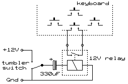
Image12.gif

relay.jpg


Now when I have come to wire this up on this relay board I have a couple of issues, one is that I now need a GND, VCC and IN1 from the relay going to my breadboard and that confused me as before I only had two wires so that threw me off.

Second I am not sure if my capacitor is the wrong size for this bank because they have transistors already in there etc?

Here is what I have and I will explain what happens when I throw the switch!

5V 1.0A USB Power
16v 220uf Capacitor
8 Channel 5V Relay Panel:
SPEC: http://www.ebay.co.uk/itm/262346134998?_trksid=p2057872.m2749.l2648&ssPageName=STRK:MEBIDX:IT


circuit.jpg


So when I toggle the switch the relay clicks, the LED on the relay comes on and then after a second the relay clicks back and the LED is pretty much out but still dimming over time. Now that is what i want! Maybe I want it to only be on for a split second rather than a full second but that's not my real issue. The issue then is if I toggle the switch the other way I want it to do the same thing cause the relay to click on and then back. Instead I get no response, and then toggling it back the other way which worked before will only work if I give it say 5-10 seconds break in the non working position, I am guessing to let the cap charge or something??

I am in a little over my head and would really appreciate some help! I just want the toggle switch to throw the relay on and then off every toggle back and forth, without having to wait for the cap / whatever it is to charge!

Can someone take a look at my wiring, have I put something in the wrong place? Is the cap I am using the wrong spec?

Thanks in advance guys and I appreciate the help thus far!
 
Each relay has its own driver transistor and, it appears, its own catching diode across the coil. If you want to use your existing toggle switch and capacitor to pulse the relay, whichever way the switch flips, I think the simplest solution would be to remove the diode, ignore the 'IN' terminal and instead connect the capacitor directly to the coil as a new input point, like this :-
RelayBoardMod.JPG
 
Each relay has its own driver transistor and, it appears, its own catching diode across the coil. If you want to use your existing toggle switch and capacitor to pulse the relay, whichever way the switch flips, I think the simplest solution would be to remove the diode, ignore the 'IN' terminal and instead connect the capacitor directly to the coil as a new input point, like this :-
View attachment 27907

Thanks for the reply!

So I would just un solder the LED and solder in the cap in its place?

Sorry if I am being stupid by the way and thank you for the diagram but I will admit I am not very good with technical drawings! With no IN would I just keep my current setup but solder the middle of the toggle directly onto the new cap in the board?

Also will this make much of a difference? Can I not get the same effect keeping the board as it is and doing everything on the BB?

I am thinking the issue is that the relay on this board has polarity where as my original setup didn't so the switch worked both ways?

Thanks again, really appreciate the help!
 
Last edited:
So I would just un solder the LED and solder in the cap in its place?
No. The LED is not the catching diode. I was taking a guess as to the coil drive arrangement, from what I could make out of the board layout. If you could post a sharp close-up pic of the relay board, so that component numbers are clearly visible, that would be helpful, as would a pic of the reverse side of the board.
Can I not get the same effect keeping the board as it is and doing everything on the BB?
That's the more complex option, since it would involve additional circuitry. As is, the relay operates briefly only when the transistor input 'IN' goes to a logic high level. You want it to operate briefly when 'IN' goes to logic low also, which means further components in a circuit yet to be designed. Your choice.
 
Ah right I see!

Thanks for the clarification, here is the close up of the board. I got the 5v and applied it directly to the pins on the bottom of the board for the relay and they only worked one way around which leads me to believe it may have an internal diode?

Thanks again!
 

Attachments

  • image.jpeg
    image.jpeg
    229.4 KB · Views: 131
  • image.jpg
    image.jpg
    143.7 KB · Views: 149
Nice pics.They confirm D1 is the catching diode for relay K1, D2 for relay K2, etc. My guess at the driver circuit wasn't too bad :).
I got the 5v and applied it directly to the pins on the bottom of the board for the relay and they only worked one way around which leads me to believe it may have an internal diode?
I doubt there's an internal diode as well as the external one.The catching diode would prevent it working both ways. Let's hope the direct connection didn't blow the diode.
 
Nice pics.They confirm D1 is the catching diode for relay K1, D2 for relay K2, etc. My guess at the driver circuit wasn't too bad :).

I doubt there's an internal diode as well as the external one.The catching diode would prevent it working both ways. Let's hope the direct connection didn't blow the diode.

Thanks very much for the explanation!

So if I replace that diode D1 with the cap, how would I wire the rest up? I am just a little confused how I wont be using the IN1 but I can keep them all independent of each other?

Sorry for all of the questions but I really do appreciate your help!
 
So if I replace that diode D1 with the cap, how would I wire the rest up?
You wouldn't connect the cap in the same way as the diode. I'll draw you a pic of the connections if you want to mod the board.
In the meantime, here's how you could add a bit of circuitry (2 resistors, 1 cap, 1 Exclusive-OR gate from a quad package) per relay to use the relay board as is if you don't want to modify the board. Note that a CD4030 package contains 4 gates, so 2 chips would be sufficient for all 8 relays.
Off&On-Pulser.JPG
An advantage of using the board as is, is that the board 'IN' input provides optical isolation of the board from the controlling input signals. Also, smaller caps can be used.
 
Ah right I see, well I don't mind modifying the board and taking out the diodes so what's the best method of doing it? Would just bypassing the diode and using the circuit in my first post suffice?

Thanks again!
 
Would just bypassing the diode and using the circuit in my first post suffice?
No. You would need to remove the diode (or at least disconnect one end), then connect the cap as shown in post #9, i.e with only one leg of the cap going to the left-hand pad vacated by the diode, the other leg connecting to the switch common only. That gives you effectively the circuit in your first post.
Incidentally, I should have mentioned that the ciruit illustrated in post #8 was just a proof of concept and gives a pulse of only ~5mS (probably not enough for a relay to pick up). The time constant defined by R1 and C1 could be increased to lengthen the pulse as necessary .

Hi again sorry I didn't see the second post you did with the diagram, that makes complete sense!

I will give this a go tonight and see how it goes thank you so much for your help and perseverance despite my lack of electronics knowledge!
 
Perhaps this will clarify the wiring. It shows the connections for relay K4 only. Note that neither the 'IN' nor the 'Gnd' terminals of the board are used: this ensures that no current can flow through the unused transistor and optoisolator components but also means that there is no LED indication of relay operation. The Vcc connection is common to all 8 relays and is used. The cap connects to the left-hand pad from which D4 has been removed.
RelayWiring.jpg
 
Perhaps this will clarify the wiring. It shows the connections for relay K4 only. Note that neither the 'IN' nor the 'Gnd' terminals of the board are used: this ensures that no current can flow through the unused transistor and optoisolator components but also means that there is no LED indication of relay operation. The Vcc connection is common to all 8 relays and is used. The cap connects to the left-hand pad from which D4 has been removed.
View attachment 27937
Thanks again this has really helped clarify what I need to do, I will have a go at getting this all linked up this evening and let you know how it goes :)
 
I wonder if contact bounce (5-10ms?) on input OR outputs will become and issue

... and what is the minimum On time, that is acceptible? 100ms?

I think the XOR cct is correct solution with debounce cap >0.1uF across input switch. This will charge fast and hold on 1st contact and hold for ~22ms with 220K and contact bounce. This can be increase to 1 or 2uF if desired to make same part as delay cap.

For 500ms relay on time, XOR delay with 220K input must be~2.2uF

5V sensitive Relay coil is 70Ω and with transistor and optoisolator with 122 value R would appear to be 1.2K which can be driven by 5V logic if it is a CMOS, 74HC86N.. Dont use a CD4030 as it cannot drive more than 1mA @5V. , typ 0.5mA

In summary you want a SPST toggle switch to be a momentary unipolar pulse thus a frequency doubler** XOR std config used as a monostable is needed here.

** This means one switch cycle produces 2 pulses
 
Last edited:
Perhaps this will clarify the wiring. It shows the connections for relay K4 only. Note that neither the 'IN' nor the 'Gnd' terminals of the board are used: this ensures that no current can flow through the unused transistor and optoisolator components but also means that there is no LED indication of relay operation. The Vcc connection is common to all 8 relays and is used. The cap connects to the left-hand pad from which D4 has been removed.
View attachment 27937

It works!! :)

Totally removed the diode, put the cap on there and connected everything up as per your last post and it worked like a charm.

Hooked up the relay to the USB keyboard I hacked apart and each flick of the toggle switch gave me on keystroke, fantastic!

I have some stripboard so I think I will send a wire from the left side of the diodes to a seperate board and put the caps on there maybe so it's a bit easier for me to manage the switches etc but apart from that I am really happy it is all working!

Thank you so much for your help, if I had tried to figure that one out on my own I think I would have torn my hair out!

Just a couple of questions on a side note, the holes on the back of the board where the diodes were connected are teeny tiny/non existent. SO I have cut the cap leg pretty short and just whacked some solder on there to keep it stuck but it's by no means a great connection. Would using a tiny drill bit to widen the hole slightly to fit the cap leg in harm the circuit? If so I may just get some wires on there and put some epoxy or something similar over the connection?

And my second question, to power this I use an iPhone plug with a USB cable so 5V and 1.0A. Could I just run wires from the keyboards power that I am attaching this to or will I end up drawing too much power from it?

Thank again!
 
Glad you've got it working.
Would using a tiny drill bit to widen the hole slightly to fit the cap leg in harm the circuit?
Possibly. Those tiny holes are called 'vias' and are actually plated to provide conduction between the front and back copper layers of the board. If you're going to mount the caps on stripboard you won't need to enlarge the holes. Just solder thin insulated connecting wires to the pads (make sure not to bridge the two pads where a diode was, or you'll have a short-circuit) and apply some epoxy or hot-melt glue to provide mechanical support for the wires.
All 8 relays active simultaneously would draw about 0.5A if my reading of their datasheet is correct, so that's within the rating of the iPhone thingy. But USB attachments usually have to negotiate with the host to determine how much current the host will provide. I've no idea if your thingy will oblige with 0.5A.
 
the Caps will see some negative V spikes that will should not exceed 10% of the forward V rating for long life on polarized caps.
 
Top