Maker Pro
Maker Pro

Modification of anti-bark control circuit - help please!

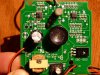
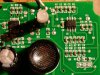
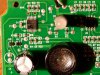
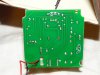
I have a circuit with a microphone and speaker that detects sustained loud noises (dog barking) and emits an ultrasonic (audible to dogs) and a sub-ultrasonic (audible to human) signal to deter the dog from barking. It's used as a training tool. PHOTOS ATTACHED!!

I find the audible to human sound very annoying and would l like to either keep the audible signal from making it to the speaker by ?shorting? that circuit OR by filtering it before it gets to the speaker.

I would also like to be able to tune the frequency of the ultrasonic output. Is it obvious whether there is a component or series of components that can be bypassed or replaced that will allow me to turn a dial and access a range of frequencies rather than just one (as it is set up now)?

While I would love to start from scratch and build a circuit that does what the one I have can do (but better), I do not have the know-how, though i've seen versions of it (not explained) using arduino circuits, etc. on line, so it's probably not very complicated. that said, please let me know if you know where instructions exist!

If you might be able to help me get started on the modifications, please let me know! I'm good with a soldering iron and am resourceful (can find electronics components if i know what i'm looking for). i recognize resistors, transformers, capacitors, etc. on the board, but i don't know how they operate in concert to make the device work.

Thanks for reading, and I look forward to getting thoughtful responses.
 

Attachments

  • P1070990.jpg
    P1070990.jpg
    140.1 KB · Views: 829
  • P1070991.JPG
    P1070991.JPG
    116.1 KB · Views: 578

davenn

Moderator
hi olive
welcome to the forums :)

good clear pics, thanks
but we would need a bit more info
what are the numbers on the two chips, U1 and U2 for a start

Dave
 
chip info on the way...

the chip surfaces are rough, but i'll see what i can do to extract the names/details
 
Chip info - much more clear after wiping away the flux?

let me know if the pics aren't clear...i'll type out the info
 

Attachments

  • P1070997.JPG
    P1070997.JPG
    49.1 KB · Views: 383
  • P1070998.JPG
    P1070998.JPG
    54.3 KB · Views: 400
  • P1070999.jpg
    P1070999.jpg
    127.8 KB · Views: 586

davenn

Moderator
yup OK

U2 is a dual Op-Amp
U1 is a PIC processor

since much of the work is going to be done within the PIC and without the code, overall circuit diag. etc for it. There's probably not a lot you could do to modify the output tones of this unit.

Dave
 
i have access to a volt-meter, and if i tried hard, i could probably get access to an oscilloscope. i wonder if i might be able to (with either of those tools) trace to the source of the audible signal and disconnect it?

filtering seems like it should be a possibility. in optics, i know i can by a band bass filter that only allows light of frequencies above a particular wavelength/energy. does the same technology exist for electronics? if so, i should be able to wire in a 'band pass filter' just before the speaker that only allows frequencies above 15000Hz, right?

any thoughts on those options?
 

KrisBlueNZ

Sadly passed away in 2015
Yes, you might be able to filter the signal. You would need to trace out the schematic though, so we can figure out how to connect the filter.

Is the human-audible signal sent through the same speaker that the ultrasonic signal is sent through? AFAIK, usually a special transducer is used for ultrasonic sounds; the human-audible sound would be sent through a separate speaker. Is this not true in this case?
 
tracing and what's coming from the speaker...

If you've got any thoughts or advice for how to trace the signal, please let me know. I may have the tools, but I don't know what I should be looking for. If I were just to guess, I'd say the easiest thing to do would be to use an oscilloscope (which i don't have (yet)) and start at the speaker +/- and go backwards from there. Is there a way to do this with a volt-meter (i have a volt meter)?

My guess is that both the audible and ultrasonic signals are emitted through the little speaker. the audible tone is very high frequency as well, so it sort of makes sense that both might be produced from the same 'speaker'.
 

KrisBlueNZ

Sadly passed away in 2015
OK. No, I don't think there's much point in tracing the signal with an oscilloscope. An oscilloscope would be useful, but first we need to know a lot more about the circuit.

The pictures you posted are good, but I really need something better to work from. I need both sides shown looking straight down on the board, well-lit but with no reflections.

Ideally, the markings on the resistors should be readable. If that means that the picture is too big to post here, post scaled-down pictures of the top and bottom, and separate close-ups of the top left and top right areas of the top side, where the dense tracks and components are.

If the human-audible sound is a very high frequency, it will be difficult to filter it out from the ultrasonic signal. I'm not sure whether it's worthwhile. But if you want, post those pictures and we'll see.
 
tracing follow up

sounds good. i'll take better pics and post later today. thanks for trying this out with me!

also, i think the audible signal, while high frequency within the human range, is not anywhere near 'our' limit of 20,000 Hz, which is really a child's limit, and the starting point for the ultrasonic range that i'm guessing this device is outputing (20,000-60,000 Hz).
 

KrisBlueNZ

Sadly passed away in 2015
True, but even if the human-audible frequency is 12.5 kHz, say, and the dog signal is 25 kHz, that's only one octave difference; you will need a fairly steep filter - at least 12 dB per octave, perhaps twice that - if you want to reduce the human-audible signal significantly without affecting the dog-audible frequency.
 

davenn

Moderator
it appears as they are using the same transducer for both signals ... no sign of any other "noise emitting" device
And the pic is being used as a 2-tone oscillator

Dave
 
detailed pics.

let me know if these aren't high detail enough. they're compressed files. i can post the full sized images online, but maybe Electronics Point won't allow the full sized images on their site
 

Attachments

  • P1080012.jpg
    P1080012.jpg
    152.6 KB · Views: 315
  • P1080010.jpg
    P1080010.jpg
    150.3 KB · Views: 300
  • P1080007.jpg
    P1080007.jpg
    148.4 KB · Views: 256
  • P1080008.jpg
    P1080008.jpg
    148.4 KB · Views: 324
  • P1080009.jpg
    P1080009.jpg
    145.4 KB · Views: 320
  • P1080011.jpg
    P1080011.jpg
    133.8 KB · Views: 338

(*steve*)

¡sǝpodᴉʇuɐ ǝɥʇ ɹɐǝɥd
Moderator
That's plenty of detail. On a technical note, taking the photos in direct sun (as you've done) creates harsh shadows and brilliant highlights. Using indirect light (i.e. in shade) will give you a better image.

However I see no immediate need for larger images than these.
 

CDRIVE

Hauling 10' pipe on a Trek Shift3
There may be hope. It's more than likely that if the audible tone is generated simultaneously with the ultrasonic tone they emanate from separate uC pins. If so you could cut the trace or remove a coupling component.

Chris
 
more of the same...or other options...

Hopefully these images tell the full story of the circuit board. Please let me know if they don't, and i can certainly diffuse the light and take new images.

- - - If filtering the audible signal is not an option, is there a way to use the circuit that detects the barking noise (and likely counts for a few seconds of sustained barking before signalling on the ultrasonic and audible frequencies) or the output of the speaker to switch on an external signal generator? I've ordered a tunable signal generator, so if this can be combined with the bark detection part of this circuit, i'd essentially have a tunable version of the same device. I realize i'd need to add an amplifier and speaker...

what do you think the best options are for either modifying by filtering or bypassing the audible signal or using parts of this circuit as a switch for an external amplified ultrasonic signal?
 
Reply to Chris - Tracing the audible and ultrasonic signals

Chris -
Can you suggest what tools I would need and how to go about tracing that signal? I can let everyone know what I find...

Thanks for the suggestion. It's what I was hoping is possible.
 
Top