Maker Pro
Maker Pro

Microcontroller project for my pool pumps

Hello everyone. I'm new here and have enjoyed reading the other threads. I have a project I'm in the final stages with and need some consultation before I do the final installation.

Project Overview:
I replaced my mechanical timers for my pool pumps with an Arduino / ESP8266 microcontroller solution

Components:
Wi-Fi based microcontroller controller with (3) relay chains.

(1) 110VAC relay switch for pool like (5VDC relay coil) (http://pic.hkyrd.com/index.php?f=Ly8vdXBsb2FkcGljL1NLVS9UMS9UMTA5Ni9UMTA5NnolMjAoMSkuanBn&u=ODY3NTU=)

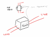
(2) 220VAC relay/contactor switches for pool pump and booster pump (24AC relay coil) (http://www.homedepot.com/p/Packard-...mp-Definite-Purpose-Contactor-C240A/203565786). Because my microcontroller doesn't deal with 24VAC, I'm using more of the relays above to switch in 24VAC to these two relays.

FYI: Raspberry PI running an MQTT server that is also involved with other home control components. This is my centralized control point for all gadgets

Problem:
I have everything working except for one issue. When I activate the pool pump relay, everything is fine, but when I close the other relay for the booster pump (main pump must be on to run booster) both pumps stop. I confirm that the smaller relays are closed, so I there is a problem on the 24VAC side. I'm wondering if I don't have enough amperage on my 24VAC power supply. I cannot seem to find any educational information for me to tell what I need to close them.

Concerns:
1) Do I need some resistance for the 24VAC relay/contactors? I have nothing there right now. Perhaps this is why I'm not able to close two at once?
2) Flyback voltage: I believe I'm protected because I'm using the two smaller relays to control the 24VAC coil line as I mentioned above. So, basically two relays for each pump. The smaller relay gets switched from my microcontroller and it closed the 24VAC for the contactor relays. This allows me to keep a AC from being anywhere inline with my project and I just wanted to keep it separate plus I thought it would protect the microcontroller.

I hope that was clear!

Many thank yous for helping the less educated! :)
 

(*steve*)

¡sǝpodᴉʇuɐ ǝɥʇ ɹɐǝɥd
Moderator
Have you tried this with a smaller load (say a light bulb) to confirm it's not something related to the load?

With dummy loads, see if you can close both contactors independently and that it's just the combination which causes problems.

Can you show us how you've wired the contactors?

What current is required by the contactors, and what is the rating of your 24VAC source?
 
What power is your 24V AC supply capable of? For 2 relays you'll probably want at least 40VA. Measure the power used by your relays and you'll know if you're exceeding your supply.
 
Thank you for the responses, folks. I was able to get more details than I was able to last night. Here is a photo of the project so that explains a few things:

https://goo.gl/photos/KWuJUvDZq6Rp5DDE9

The two contactor relays are on the left. The smaller relays feed the coils for those as well as a pool light. The ESP8266 board is on the lower right.

eKretz, per your comment, this power supply is only 20VA, so that may be my issue.

1) how do I verify what I really need for them? Their spec sheet is garbage...no detail
2) do I need any resistance to keep the current down when closing the relay coil?

Again, thanks everyone.
 

(*steve*)

¡sǝpodᴉʇuɐ ǝɥʇ ɹɐǝɥd
Moderator
Firstly, please upload your images here. It can be a pita on a mobile platform to view images on Third party websites which fsck about with exciting their pages.

Secondly, I note you have not tried what I suggested in my first post.

Thirdly I note you don't have any base resistors and only have a protective diode on one of your relays.

Fourthly, you call them relays (or i assume these are what you are calling relays) but they seem to require external power. What are they?

Fifthly, I think you referred earlier to a datasheet but didn't provide a link to it. Can you provide a link?
 
I will run the tests again tomorrow morning more thoroughly and share the data. Wanted to upload the photos so you can view them easier.

Couple of points:
1) smaller relay work great. I've tested them well. My understanding is that flyback protection is built into them. I bought off eBay and they don't have much of a schematic. :/ Lot of posts out there with people using them successfully.
2) I've tested the AC power supply with the relays, but not together. I will include that test tomorrow. Part of my request for help was understanding how to measure and calculate the needs. I'm not finding good information on how to do this after hours of searching. These are the specs for the contactor relays: http://packardonline.com/Shop/Product/2512
3) similar to above, I'm not an electronics person. This is one of my first projects like this, so part of my question was IF I needed a resistor inline with the relay coil. I'm looking for any direction / pointing me where I can get more education.

More info to come tomorrow. I'm definitely having fun learning with this project.
 

Attachments

  • poolHousePhoto.jpg
    poolHousePhoto.jpg
    183.7 KB · Views: 127
  • schem.jpg
    schem.jpg
    95 KB · Views: 98

(*steve*)

¡sǝpodᴉʇuɐ ǝɥʇ ɹɐǝɥd
Moderator
You're right, there is not much information about that contactor. I tend to lean toward the argument that you have insufficient power at 24VAC to close both of them.

Have a look here to see the correct way of using a transistor to switch a load. The way you have drawn your circuit, you could damage your microcontroller or the transistor.
 
You can check what they need by measuring the current used when they are energized. Put a multimeter in line to measure amperage.
 
Great tips, guys.

I did a test w/ just the power supply hooking it up to the relays and it did the same behavior as when it was hooked up to my controller. Main pump will trigger and then when I engage the second relay, it disengages the first one.

I don't have a darn AC ammeter, so I can't test the load. Bummer...

I'll start looking into transistor to switch the load link you sent, Steve.
 

CDRIVE

Hauling 10' pipe on a Trek Shift3
Personally I wouldn't suggest measuring current to a nube. It's a better suggestion to measure the coil resistance. Power disconnected of course. You can also measure the 24VAC voltage source while the contactors are being energized to see if it drops significantly. That said it's doubtful (with the information given thus far) that there's many of us that don't surmise that the 24V is probably being pulled down below the contactor's dropout voltage.

BTW, the above was written but not posted about 45 minutes ago. I've spent that 45 minutes searching for the coil resistance of the Packard C240A. It must be a closely guarded secret because I found bubkis! :confused:

Chris
 
Last edited:
Chis, I was laughing my rear off when I read your post. I've been there not once, but a few times in search for details. Almost disbelief that the specs aren't readily available...somewhere. However, I just chalked it up to my noob-ness. :)

I did measure the coil impedance. Depending on where I placed the meter, it ranged from 0.6 - 0.8 Ohms. Correct me if I'm wrong, but isn't this about 30-40 VA given that range? Remember, this is an A/C coil. And, I have two relays.

So, as I've continued to learn a bit further even since posting this and getting confirmation, my 20VA power supply seems like the medal count of a small country in an international Olympics.

If this is the situation, would you think a 40VA adapter like this would work? I saw a 50VA somewhere, too. BTW, my software prevents them from triggering at the same time. There's a 30s delay for the second relay no matter what.

Again, I appreciate the feedback. I'm enjoying this.
 
Good point Chris. I didn't think about that.

Shawn, that coil resistance doesn't sound remotely right. Your relays would draw 30 - 40 amps each when energized if it was. How are you checking this?
 

CDRIVE

Hauling 10' pipe on a Trek Shift3
Shawn, I'll echo what eKretz said. I just happened to have a honking GE (CE353A) Contactor within arms reach of me. It's a 3 pole model with the following ratings...

Coil Voltage: 24VAC
Contacts VAC: 240V, 480V, 600V
"FL" (Full Load Inductive Amps): 30A
"LR" (Locked Rotor Amps): 180A, 150A, 120A
Resistive Amps Per Pole: 40A

Now this beast measures a coil resistance of 6.8Ω, which is far more reasonable than the 0.6Ω to 0.8Ω that you're measuring. Did you insure that the transformer was disconnected from the contactor coil when you measured the coil's resistance?

Chris
 
The resistance will not tell you how much current is drawn for an AC coil.

But, based on the low resistance reading, I think the terminals have been identified wrongly.

Bob
 
Great info, guys. I'm thinking through the details and researching so I can better understand. Here is a diagram and exactly what I did. (attached)

In the top view, I disconnected the wiring from the relay coil terminals and put my Fluke meter exactly where the arrows go on the terminals. The 220V line and load sides stayed as I didn't think that would make a diff to the coil reading.

Did I do something wrong? Is my Fluke out of calibration?
 

Attachments

  • 220V-ContactorRelays.png
    220V-ContactorRelays.png
    453.8 KB · Views: 107
Oh, I see where that was misleading. Those terminals are for daisy chaining I presume, so they put two terminal legs onto each side, but they are one piece of metal. So, answer is 'no' there are only two coil terminals.

In terms of shorting the leads together, do you mean on the Fluke? If so, I have done that and it beeps as a dead short. I'm happy to try whatever you recommend when I get home today. I'm in California.
 
Top