Maker Pro
Maker Pro

Microcontroller LiPo Charger

Hi All,

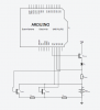
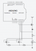
As a novice, I am attempting to design a micro controller LiPo battery charger with state of health monitoring. I have produced a very basic circuit diagram and would appreciate it if somebody with a sound knowledge of electronics could cast their eyes over it and assess the circuit for feasibility and whether or not it will function as expected.

The circuit is designed to charge a single cell LiPo using a CC/CV approach, with a PWM controlled MOSFET. The state of health monitoring is implemented using a dual pulse method, where an initial small load is applied to the battery to stabilise the discharge, then a larger load is applied and the battery voltage measured. The internal resistance can be worked out using this voltage, the load resistance and the open cell voltage.

Any thoughts will be much appreciated!
 

Attachments

  • Screen Shot 2015-10-30 at 13.45.18.png
    Screen Shot 2015-10-30 at 13.45.18.png
    38.9 KB · Views: 163
Hello James, welcome to EP. Your MOSFETs appear to be enhancement type, is this correct. Your Charging MOSFET looks like it's upside down. Check where your source connection should be for a P-Channel type. Also how is this circuit going to supply constant current? What charging voltage are you using? You will also need a timer to switch off charging in the event of circuit sensing malfunction after a pre-set about of time dependant on the battery capacity.
Thanks
Adam


Hi Adam, thanks for your comprehensive reply. Yes, the MOSFETs are enhancement type, I want them to turn on when I apply a gate bias voltage. Perhaps I will need a logic type MOSFET to interface with the Arduino outputs? I have changed the MOSFET types to enhancement N type. I am using 4.2v on the charging rail, as the maximum voltage of a charged LiPo battery is 4.2v. Constant current is provided via a current measurement made with the Arduino analogue inputs, and a software algorithm to change the charging MOSFET gate bias accordingly. The cell voltage is also measured using the analogue inputs on the Arduino to allow a switch between constant current and constant voltage charging. Your suggestion of a failsafe timer is a good one, thanks. I have attached an updated circuit diagram.
 

Attachments

  • Screen Shot 2015-10-30 at 16.40.32.png
    Screen Shot 2015-10-30 at 16.40.32.png
    34.8 KB · Views: 117
You mean you have changed them to depletion mode? How is your Arduino going to control the charging FET. Your gate driving voltage will need to be quite a bit higher than the battery voltage for it to conduct enough current. You can change the average current through the FET using PWM but you can't produce constant current. Your current will decrease as the battery voltage rises.
Adam

What I would like to happen is for current to flow through the MOSFET when the gate source voltage is higher than the source voltage. I thought that an enhancement mode MOSFET would satisfy that, but I may well be wrong. Yes, I hadn't thought about the gate source voltage. If the output of the Arduino is 5v max and the max source voltage is 4.2v, 0.7v gate bias voltage may not be enough to turn the MOSFET on. I will have a look around to see if anything exists with a bias voltage lower than 0.7v. The charging algorithm will employ a feedback loop to ensure that as the battery voltage rises, the current will stay constant until constant voltage charging is required.
 
How will the current stay constant? Please explain.
Adam
Thanks for the FET diagram, I will implement that in the circuit.

The shunt resistor allows the Arduino to measure the drain source current, and the charging algorithm changes the PWM signal to adjust the current accordingly. It will be an average current, yes. I could use a capacitor smoothing circuit to provide a more constant current source for the battery.
 
Ok you won't get constant current unless you adjust the charging voltage as the voltage of the battery increase. You can't do that. What you will be doing is supplying shorter or longer pulses of a current that will be dependant on the voltage difference between the supply voltage and the battery voltage divided by the total resistance of the MOSFET and the series resistor. We need to just clear that up!
Thanks
Adam
 
OK, thanks Adam. What I am trying to do is implement the circuit diagram attached (minus the internal resistance test circuitry) to charge the single cell LiPo. Is this dramatically different to my circuit design?
 

Attachments

  • Screen Shot 2015-10-30 at 19.28.30.png
    Screen Shot 2015-10-30 at 19.28.30.png
    30.4 KB · Views: 95
I guess my next question is then do you see anything inherently wrong with that circuit? I understand that circuit to be an implementation of a CC/CV charging method.
 
Creating a battery charger is way beyond your capabilities.

You can buy single cell INTELLIGENT chargers on eBay for $2.00

These have taken hundreds of hours of design-work to develop, and you think you can put one together in an afternoon.
 
This is a small part of a research project into battery health trend monitoring as part of my undergraduate degree. Electronics is not my specialty, but I can assure you it is well within my capability to learn how to build a basic charging circuit to equip me to undertake the real research!
 
I guess my next question is then do you see anything inherently wrong with that circuit? I understand that circuit to be an implementation of a CC/CV charging method.

My personal preference James would be to use a constant current regulator which you then bypass when you switch over to constant voltage. Lithium batteries as you know do not like being overcharged at all, so you have to be very careful that you don't. You could look at using this device set up for constant current. You will need a higher voltage than 4.2 on the input to take into account circuit losses. This also means you will need a 4.2 voltage regulator for the constant voltage part of the circuit. I don't see any reason why you can't use another LT1083 for this. Consult the data sheet for correct operation. Also if you don't already know, then fully understand yourself the correct the charging procedure of lithium batteries and make sure you have all the necessary safety features in place. This may also include temperature monitoring.
Thanks
Adam
http://cds.linear.com/docs/en/datasheet/108345fh.pdf
 
Last edited:
Top