Hello.
I'm making a sewable electronics project. I originally intended to use a board based on ATTiny 85, but I've run out of practical ways to drive them considering the pin amount. It's to be fitted in a glove and powered by a power bank. I'm planning on using an Arduino pro micro instead

I'm using lilypad LEDs which come with 100Ω SMD resistor and should have a 20 mA test condition current draw, though I'll say I didn't get them through a reputable source, that source reports 40 mA.
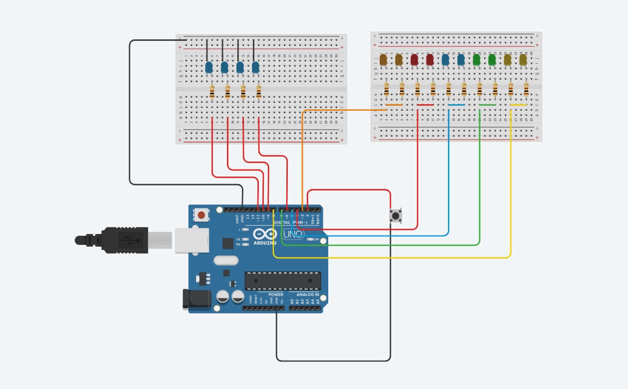
The first four set of blue LEDs will follow a blinker pattern similar to some cars. It's a variation on a standard PWM fade. With the press of the button, they will stop blinking and be fully lit. Another press of the button will light up the 10 LED array. At 20 mA @ piece, that should be 200 mA max with 40 mA per pin going from the 20mA estimate.
I would love to power this with my original ATtiny based board as that is made for wearables. This concept can be used, but due to pin restrictions, I would need some way of powering the large array. I made a concept where I use a slide switch to move current from the last pin on the 4 LED array to the entire 10 LED array. (Before I realised this isn't possible) But maybe I could use the pin as a signal to turn on a driver of some sort? Still, this adds complexity that may be quite hard to add in a wearable project.
My questions:
I can probably improve my code, though it works in this state. Any suggestions? I would, of course, delete anything serial related.
How could I test the amperage usage from the LEDs and get a reliable result? I have a multimeter.
Is it feasible to drive the LEDs like this? Are the max currents very strict, as in it will break down if I exceed them?
Has anyone ever used an Arduino micro with conductive sewing thread?
How could I power this using the original ATtiny85, making it as small as possible? (Even if I probably won't do this, I'm interested in learning)
I'm making a sewable electronics project. I originally intended to use a board based on ATTiny 85, but I've run out of practical ways to drive them considering the pin amount. It's to be fitted in a glove and powered by a power bank. I'm planning on using an Arduino pro micro instead

I'm using lilypad LEDs which come with 100Ω SMD resistor and should have a 20 mA test condition current draw, though I'll say I didn't get them through a reputable source, that source reports 40 mA.
The first four set of blue LEDs will follow a blinker pattern similar to some cars. It's a variation on a standard PWM fade. With the press of the button, they will stop blinking and be fully lit. Another press of the button will light up the 10 LED array. At 20 mA @ piece, that should be 200 mA max with 40 mA per pin going from the 20mA estimate.
Code:
#include <Button.h>
const byte ledPins[4] = {6, 9, 10, 11};

Button blinkLed(2);

int n = 0;

void setup() {
  blinkLed.begin();

  Serial.begin(9600);

  for(int i = 0; i <= 3; i++){
    pinMode(ledPins[i], OUTPUT);

  }

}

void loop() {
  if (blinkLed.pressed() && n == 0) { //if n indicates LED = off with n=0, start blinker program
   n++;
   Serial.println(n);
    while(n == 1){
    for(int i = 0; i <= 3; i++){
    for(int j = 0; j <= 255; j+=2){
    analogWrite(ledPins[i], j);
    delay(1);
    }
  }
    for(int i = 0; i <= 3; i++){
    for(int j = 255; j >= 0; j-=2){
    analogWrite(ledPins[i], j);
    delay(1);
    }
  }
      if (blinkLed.pressed() && n == 1){ //if n indicates LED = blinker start small flashlight
        n++;
        Serial.println(n);
           while(n == 2){
            digitalWrite(6, HIGH);
            digitalWrite(9, HIGH);
            digitalWrite(10, HIGH);
            digitalWrite(11, HIGH);

            if (blinkLed.pressed() && n == 2){ //if n indicates LED = small flashlight, turn off small flashlight and start big flashligh
              n++;
              Serial.println(n);
              digitalWrite(6, LOW);
              digitalWrite(9, LOW);
              digitalWrite(10, LOW);
              digitalWrite(11, LOW);
              while(n == 3){
                digitalWrite(3, HIGH);
                digitalWrite(4, HIGH);
                digitalWrite(5, HIGH);
                digitalWrite(7, HIGH);
                digitalWrite(8, HIGH);

                if (blinkLed.pressed() && n == 3){ //if n indicates LED = big flashlight, turn off
                n = 0;
                Serial.println(n);
                digitalWrite(6, LOW);
                digitalWrite(9, LOW);
                digitalWrite(10, LOW);
                digitalWrite(11, LOW);
                break;


                }
            }
          }
        }
      }
    }
  }
}
I would love to power this with my original ATtiny based board as that is made for wearables. This concept can be used, but due to pin restrictions, I would need some way of powering the large array. I made a concept where I use a slide switch to move current from the last pin on the 4 LED array to the entire 10 LED array. (Before I realised this isn't possible) But maybe I could use the pin as a signal to turn on a driver of some sort? Still, this adds complexity that may be quite hard to add in a wearable project.
My questions:
I can probably improve my code, though it works in this state. Any suggestions? I would, of course, delete anything serial related.
How could I test the amperage usage from the LEDs and get a reliable result? I have a multimeter.
Is it feasible to drive the LEDs like this? Are the max currents very strict, as in it will break down if I exceed them?
Has anyone ever used an Arduino micro with conductive sewing thread?
How could I power this using the original ATtiny85, making it as small as possible? (Even if I probably won't do this, I'm interested in learning)
