Hi,
I just recently run into problem to replace functionality of mechanical relay with semiconductor. Little change from relay is that is should be unidirectional for conductive DC positive only as attached schematic bellow. I already check many articles on internet, there was some suggestions, but at end not all my needs was fulfill.

schematic 1
Solutions I checked:
1. P-MOSFET , fast enough also other characteristic satisfactory, but thanks to protective (body) diode can also conduct in opposite direction. Didn't find any MOSFET without diode.
2. Solid state relays:
They can carry only switch ground (either used NPN transistor or N-MOSFET) or they have triacs which will conduct even when control signal is turned off. I saw also with dual MOSFET, but I find it to carry maximum 1A, I expected to have at least 2A.
3. Use PNP transistor with diode. I have low voltage battery in system, cannot drop more than 0.25V. For such currents (2A or more) drops are usually much higher.
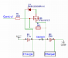
So far best I came with is dual MOSFET schematic.

Even when open is bi-directional, I control directionality via G electrode, so I can close it (I didn't put details such as resistor to clamp G to VCC, etc. schematic is just for illustrative purposes). My concern here is if diode can handle the same current as MOSFET (I expect that voltage can), also not sure how much voltage drop will be and speed as well (expectation is somewhere around microseconds). Control signal will go from N-MOSFET which will be driven by 3.3V logic.
Will appreciate if you someone can help me out with my problem.
Thx
I just recently run into problem to replace functionality of mechanical relay with semiconductor. Little change from relay is that is should be unidirectional for conductive DC positive only as attached schematic bellow. I already check many articles on internet, there was some suggestions, but at end not all my needs was fulfill.
schematic 1
Solutions I checked:
1. P-MOSFET , fast enough also other characteristic satisfactory, but thanks to protective (body) diode can also conduct in opposite direction. Didn't find any MOSFET without diode.
2. Solid state relays:
They can carry only switch ground (either used NPN transistor or N-MOSFET) or they have triacs which will conduct even when control signal is turned off. I saw also with dual MOSFET, but I find it to carry maximum 1A, I expected to have at least 2A.
3. Use PNP transistor with diode. I have low voltage battery in system, cannot drop more than 0.25V. For such currents (2A or more) drops are usually much higher.
So far best I came with is dual MOSFET schematic.
Even when open is bi-directional, I control directionality via G electrode, so I can close it (I didn't put details such as resistor to clamp G to VCC, etc. schematic is just for illustrative purposes). My concern here is if diode can handle the same current as MOSFET (I expect that voltage can), also not sure how much voltage drop will be and speed as well (expectation is somewhere around microseconds). Control signal will go from N-MOSFET which will be driven by 3.3V logic.
Will appreciate if you someone can help me out with my problem.
Thx