Hi everybody. Upfront I want to let you know, that due to my serious health problems I am slow in progressing in my experiments.
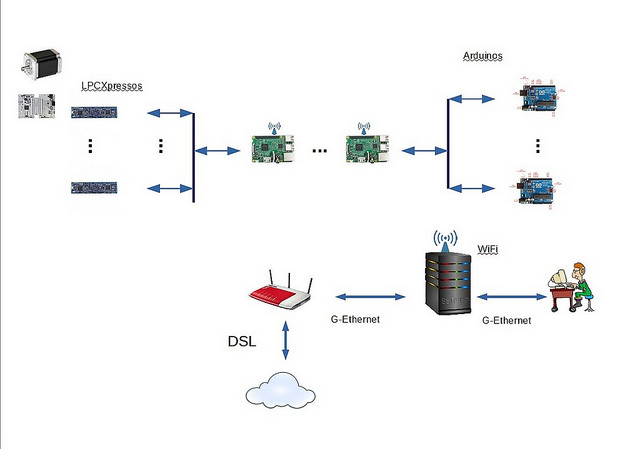
Its know quite a time ago that starting to experiment and learn how to do it I did use PyCharm IDE from Jetbrains to program my experiments on the RaspBerry Pi's. I had no experience in using Linux and never really went in depth into the topics around communication. I do have a PC with Windows and do use it as my development workstation. In the graph here that I did I show the IT infrastructure I am establish in in my private lab. I do sit on my PC and have the RaspBerry Pi's contacted via WiFi. The small antena symbols show this. My first hand goal is to develop y sheet control system for my model sailboat, to model critical parts of it using the modelling language Modelica and Mathematica to do HiL and SiL,to verify that the models actually reflect the true behaviour of the subsystems modeled.
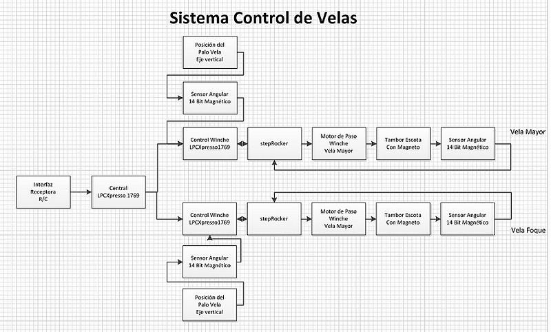
The text in the graphic was targeted for spanish speaking audience, sorry. So deviating from the hardware modules shown in the block diagram I am using for my experiments a RaspBerry Pi board to control the LPCXpresso board listed.
So I had no problems to have the Raspberry Pi desktop to show up in a window on my PC, then using Windows 7 Ultimate 64 bits. I did use ssh, secure shell to establish the communication between the PC and multiple RaspBerry Pi boards. I was also able to have the PyCharm IDE running on my PC, that generates Python code to be executed on the RaspBerry Pi, short Raspi, by defining as the remote interpreter to be the one running on Raspian Jessie on my Raspi boards. I also do want to mention that I do have my Windows constantly updated and have powerful protection software suite in place. The starting point of my failure was to publish de Raspi boards on a DNS supplier in the internet, so that I was able to have the DNS to assign the proper IP ID to a communication.
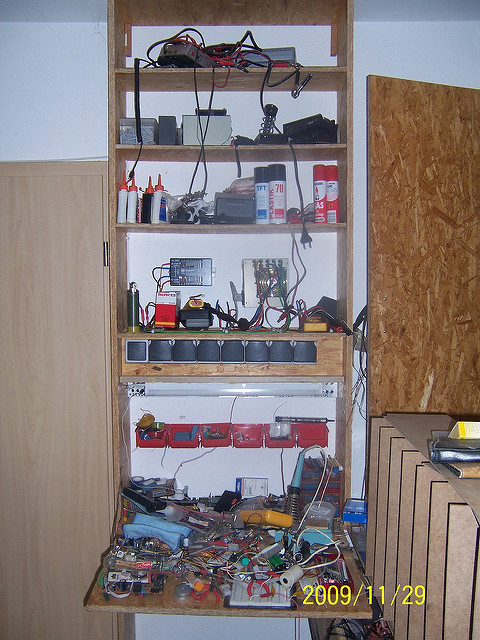
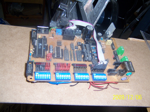
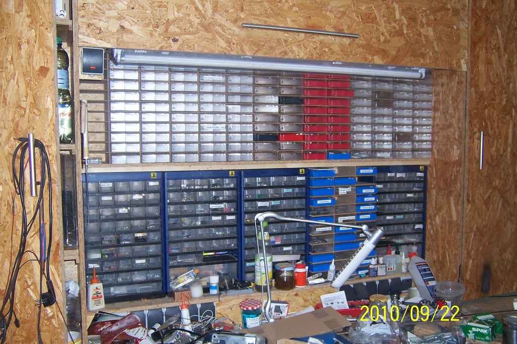
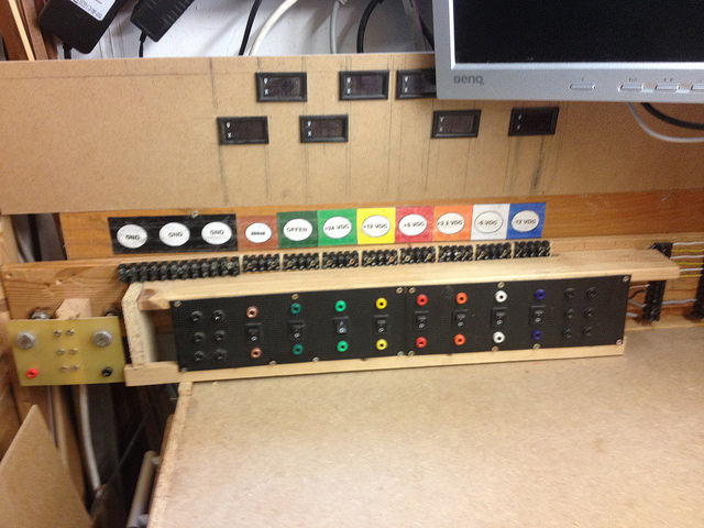
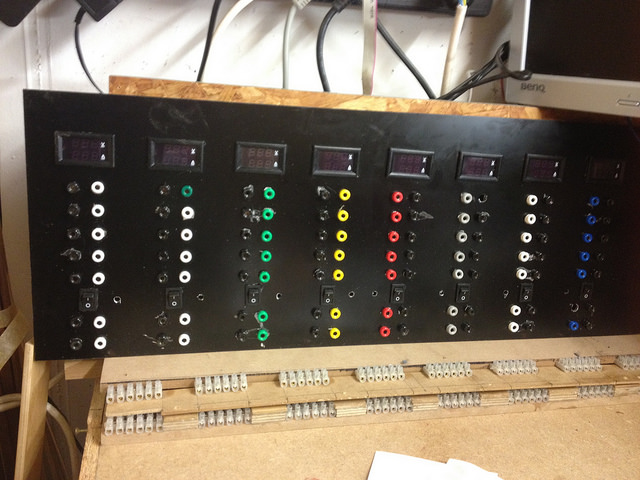
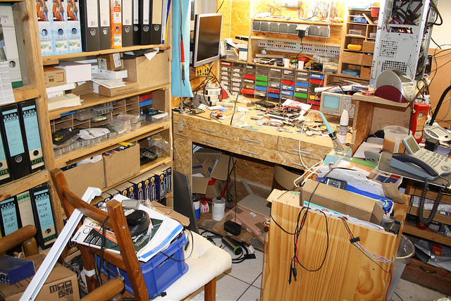
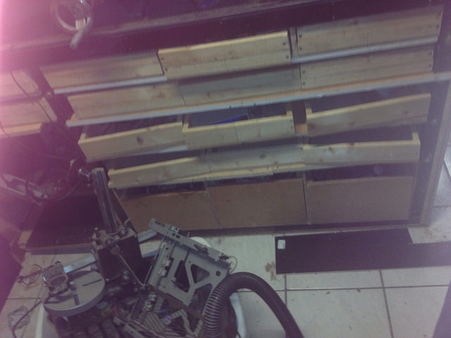
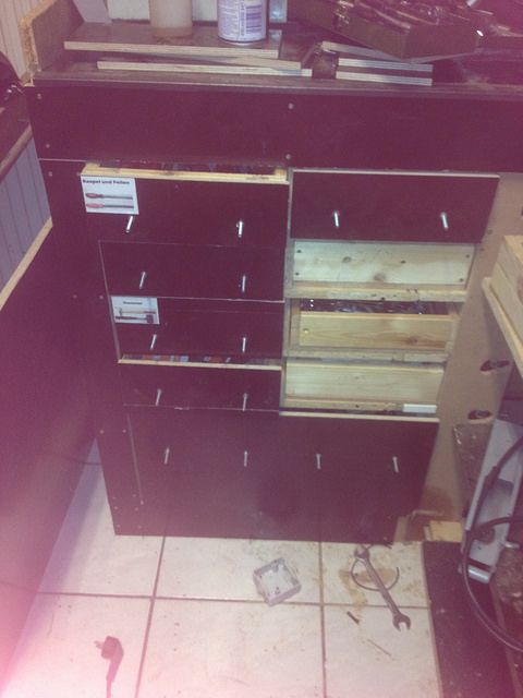
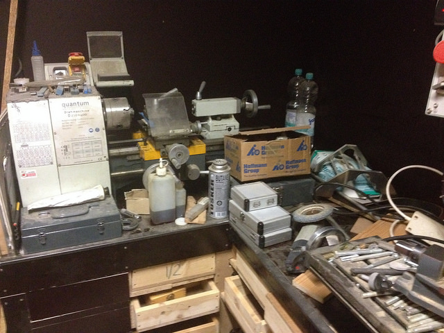
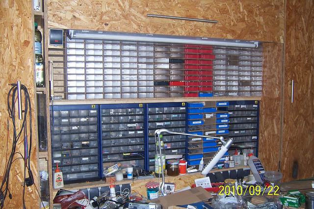
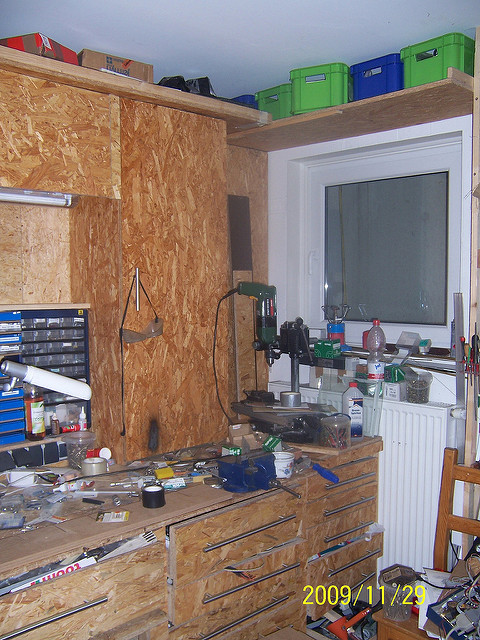
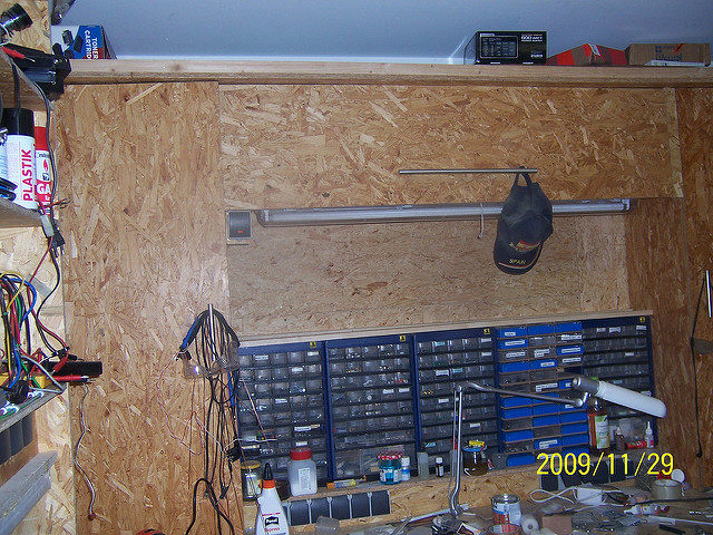
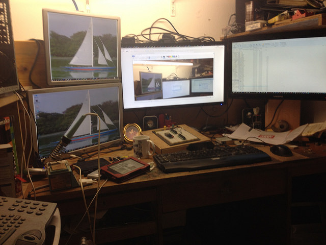
Via the Internet and the Raspi communication link between the Raspis and my PC the attackers were able to render my PC inoperable! The good in the bad was that as all my intents to repair Windows on my PC failed, I did take advantage of Microsoft's offer to have my Windows OS updated to Windows 10 Pro , which then did fully operate again. Just for your entertainment here a picture of my electronics lab which is next to my office desk in my workshop:
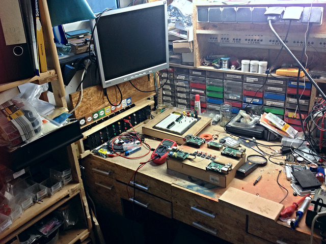
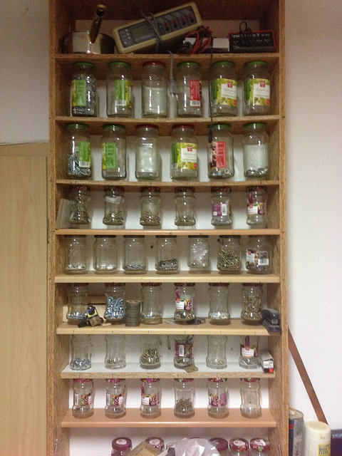
I am working since many years in developing my workshop to get it to a degree of order so that I do know what I have and where it is.
Let's continue with the main story of this thread of mine. Having suffered this successful attack I did decide to learn what is involved to understand how to have my IT infrastructure to be as safe as reasonably posible. The link to the Internet has to be kept as I do want to have access to my sailboat model via TCP/IP. I am using the term TCP/IP and not i.e. WiFi or WLAN as with the technological advances around the IoT and IIoT or Industry 4.0 are making huge improvements and many offers how to establish a wireless communication. My phone provider i.e. offers for 1 Euro a month 100 MB of data volume, much more than a communication between my model and myself on a pond would need. Exception being if I want to have video streaming capabilities. Here I can book higher data volumes for just a single day. So this possibility to use celular data communication for my model is now realistic.
So I started learning Linux using books from a german university profesor seen as a guru and valuable source to learn facts about Linux. I did also start learning about the technologies to reduce potential attack surfaces in general and in embedded systems specifically. The MOOC's, university courses available for free are excellent sources to learn. Soon I run into realizing that profesional developers frequently do their development work using virtual machines on their workstations. Virtual machines, short VM's, do isolate the host, in my case a PC running Windows 10 Pro from the VM. Should an attacker be successful in attacking my experiment setup I just have to close the VM and reopen with a status previous to the attack. In the Windows environment 2 major suppliers of virtualization tools are Oracle with VirtualBox and Hyper-V from Microsoft. I started with VirtualBox to learn that VirtualBox does not work in Windows 10 if the BIOS setting of a host PC has the Hyper-V services activated. Hyper-V are services that take advantage of hardware functionality in the Intel CPU for virtualization, a key factor to establish an efficient VM! There was also another issue linked to have the Hyper-V services activated, but later more to it! So I tried Hyper-V and could generate a VM with Ubuntu 16.04 TLS running within it. I had also no problems in having the PyCharm IDE installed on this VM and the Jetbrains licensing scheme here is very open to have the multiple instances of PyCharm running in parallel or at least available both on the Host OS as on the Linux running within the VM. Here is the point where I am right now in my efforts related to this.
Virtualization is a mature technology in the server arena and is being used there for decades now! Having virtualization applied in the embedded arena, mainly for security reasons being mandated by governmental laws for devices connected to the Internet is a different story! System resources in embedded systems are scarce by definition compared to those in servers! This made me aware of the functionality of hypervisors, type 1 and type 2 exist.
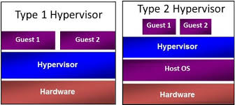
As the picture illustrates, hypervisor type 1 execute "bare metal". The term meaning running directly on the hardware, same as any code we in electronics write for Arduino i.e.! Xen being one of those hypervisors. Type 2 hypervisors do run as an application on top of a host OS, in my case Windows 10 Pro and the program Hyper-V having the role of a Hypervisor type 2. As guests are meant VM'S! The picture makes evident that a Hypervisor Type 1 can be implemented demanding much less resources. For my experiments I will experiment with y type 2 kind of solution running on top of Raspian Jessie on my Raspis! If this is properly executing y am considering also running VM on my Raspi for safety purposes! But that is on my agenda for my hobby! Studying virtualization in depth under the perspective of implementing security made me aware of another technology that can realize even implementations with demand for less resources, is called Containerization and the tool is Docker.
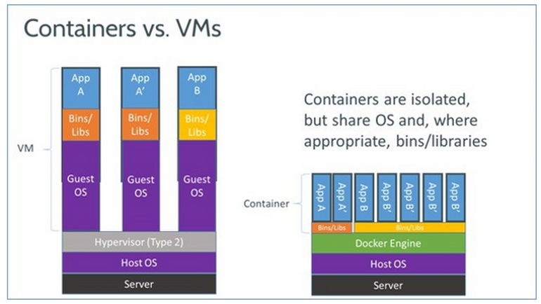
This picture illustrates the concept of Containers versus virtual machines! Containers generated using Docker run on top of the host OS and of the Docker engine, but each container does contain only those resources needed to execute while not replicating the entire OS as it takes place in a VM! But while VM's offer the best isolation and in consequence the higher safety compared with Containers whose isolation is more similar to that of one application to another application being executed within an OS. Well known to be much weaker. Due to the paramount importance of safety in devices connected to the Internet and how scarce hardware resources are in an IoT compared to a full fledged PC, a hybrid is being researched for to combine the benefits of both.
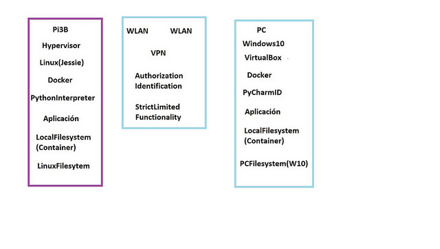
So conceptually I am aiming to implement what is shown in this graphic! I will now go into the details as it would be even more extended is this contribution already is. But the goal is to benefit to the degree reasonable and performant enough for my objectives both in my electronic workshop and for the implementation of the electronics in my model sailboat! But I do want to mention that as not being an expert I was able within less than 30 minutes to generate a Container, write a PC of code in Python for it and generate the "Hello world" message on my PC!
Taking advantage of a special offer by one of my preferred publishing companies, Packt, I could by at a very low price 5 books that cover a wide area of information regarding Docker and Containers. A lot of safety can be achieved in a Container by being very strict in defining parameters that define who might engage a communication and what each task absolutely requires to be authorized to. This applies to the OS itself, to the VM's and to Docker. Well defined parameters allow to make penetrating an expensive task. Not really having anything worth the effort, attackers might decide to go for more fruitful targets!
Finally I want to include in this contribution that the requirement of safety is making research and implementation of technologies to achieve safety in devices connected to the Internet an activity with very "deep pockets"!
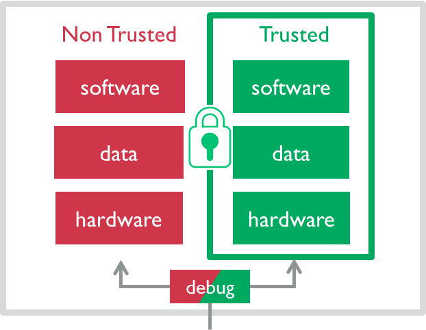
All major providers driving the development of technologies have their way to it, but as devices in the IoT and IIoT dominantly are based on controllers based on ARM technology. The core of this technologies is to have 2 different environments, Trusted, here in green, and Non Trusted, here in red. Non Trusted is microcontroller functionality as we all are aware of. If we take the Raspis as an example. Linux runs in 2 privilege modes. One being the user mode as we know it from any operating system and one is a privileged mode in which Linux kernel is executed and which enables the OS to administer the use of system resources by an application and protecting the execution of the applications by preventing them to interfere.
For the Trusted Zone ARM has defined a new even higher priority level and its execution alone allows the use of special instructions which operate on the special hardware resources available within the "TrustedZone" has the concept is called by ARM. A hypervisor is the one that executes code in this highest privilege mode that allows for efficient operation of VM's! The first 2 ARM Cortex M controllers published and licensed by ARM are the ARM Cortex M22, which is equivalent in performance to the ARM Cortex M0 and M0+. The ARM Cortex M33 is the one equivalent to ARM Cortex M3 and M4! The one most visible to me is the implementation of this technology by NXP Freescale and its i.MX8 product family. NXP is mainly targeting the automotive marketplace with this products and as a consequence the i.MX8 that comes in the following flavours
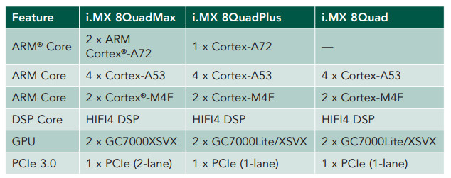
represents a device of a complexity far beyond what we are used to. This is on one side reflected by the hardware functionality shown in the table and can be, to my believe. better visualized seeing their Multisensory Enablement Kit offering:
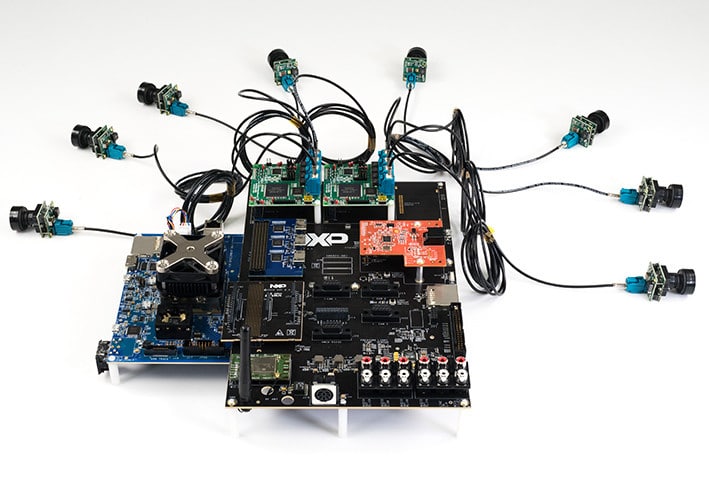
This complexity is due to the fact that it enables to create one central Unit for multiple functionality present in current top of the notch cars and those to come in a relatively close future. Development requires different engineering skills for different functionalities offered within the controller! Former Freescale announced this controller a couple of years ago and is closely working with selected tier 1 customers to use their device in the automotive marketplace. Just very recently a company that offers inexpensive boards using the previous generation controllers, i.MX6 and i.MX7 has announced to have a board in its pipe with the i.MX8.
But this complexity also demands from NXP to deliver IDE and libraries and application notes that make the implementation of this multiple functionalities possible to smaller engineering groups. While NXP had announced the availability of its i.MX8 devices sometime in 1Q17, this has not yet taking place. No wonder as to be ready to help interested customers of tier 2 and beyond demands a different class of support that has to be equivalent to the level of support we have been familiar with other products in the market. I believe this to be the reason for the still continuing delay of the general market to have access to this product!

Its know quite a time ago that starting to experiment and learn how to do it I did use PyCharm IDE from Jetbrains to program my experiments on the RaspBerry Pi's. I had no experience in using Linux and never really went in depth into the topics around communication. I do have a PC with Windows and do use it as my development workstation. In the graph here that I did I show the IT infrastructure I am establish in in my private lab. I do sit on my PC and have the RaspBerry Pi's contacted via WiFi. The small antena symbols show this. My first hand goal is to develop y sheet control system for my model sailboat, to model critical parts of it using the modelling language Modelica and Mathematica to do HiL and SiL,to verify that the models actually reflect the true behaviour of the subsystems modeled.

The text in the graphic was targeted for spanish speaking audience, sorry. So deviating from the hardware modules shown in the block diagram I am using for my experiments a RaspBerry Pi board to control the LPCXpresso board listed.
So I had no problems to have the Raspberry Pi desktop to show up in a window on my PC, then using Windows 7 Ultimate 64 bits. I did use ssh, secure shell to establish the communication between the PC and multiple RaspBerry Pi boards. I was also able to have the PyCharm IDE running on my PC, that generates Python code to be executed on the RaspBerry Pi, short Raspi, by defining as the remote interpreter to be the one running on Raspian Jessie on my Raspi boards. I also do want to mention that I do have my Windows constantly updated and have powerful protection software suite in place. The starting point of my failure was to publish de Raspi boards on a DNS supplier in the internet, so that I was able to have the DNS to assign the proper IP ID to a communication.
Via the Internet and the Raspi communication link between the Raspis and my PC the attackers were able to render my PC inoperable! The good in the bad was that as all my intents to repair Windows on my PC failed, I did take advantage of Microsoft's offer to have my Windows OS updated to Windows 10 Pro , which then did fully operate again. Just for your entertainment here a picture of my electronics lab which is next to my office desk in my workshop:

I am working since many years in developing my workshop to get it to a degree of order so that I do know what I have and where it is.
Let's continue with the main story of this thread of mine. Having suffered this successful attack I did decide to learn what is involved to understand how to have my IT infrastructure to be as safe as reasonably posible. The link to the Internet has to be kept as I do want to have access to my sailboat model via TCP/IP. I am using the term TCP/IP and not i.e. WiFi or WLAN as with the technological advances around the IoT and IIoT or Industry 4.0 are making huge improvements and many offers how to establish a wireless communication. My phone provider i.e. offers for 1 Euro a month 100 MB of data volume, much more than a communication between my model and myself on a pond would need. Exception being if I want to have video streaming capabilities. Here I can book higher data volumes for just a single day. So this possibility to use celular data communication for my model is now realistic.
So I started learning Linux using books from a german university profesor seen as a guru and valuable source to learn facts about Linux. I did also start learning about the technologies to reduce potential attack surfaces in general and in embedded systems specifically. The MOOC's, university courses available for free are excellent sources to learn. Soon I run into realizing that profesional developers frequently do their development work using virtual machines on their workstations. Virtual machines, short VM's, do isolate the host, in my case a PC running Windows 10 Pro from the VM. Should an attacker be successful in attacking my experiment setup I just have to close the VM and reopen with a status previous to the attack. In the Windows environment 2 major suppliers of virtualization tools are Oracle with VirtualBox and Hyper-V from Microsoft. I started with VirtualBox to learn that VirtualBox does not work in Windows 10 if the BIOS setting of a host PC has the Hyper-V services activated. Hyper-V are services that take advantage of hardware functionality in the Intel CPU for virtualization, a key factor to establish an efficient VM! There was also another issue linked to have the Hyper-V services activated, but later more to it! So I tried Hyper-V and could generate a VM with Ubuntu 16.04 TLS running within it. I had also no problems in having the PyCharm IDE installed on this VM and the Jetbrains licensing scheme here is very open to have the multiple instances of PyCharm running in parallel or at least available both on the Host OS as on the Linux running within the VM. Here is the point where I am right now in my efforts related to this.
Virtualization is a mature technology in the server arena and is being used there for decades now! Having virtualization applied in the embedded arena, mainly for security reasons being mandated by governmental laws for devices connected to the Internet is a different story! System resources in embedded systems are scarce by definition compared to those in servers! This made me aware of the functionality of hypervisors, type 1 and type 2 exist.

As the picture illustrates, hypervisor type 1 execute "bare metal". The term meaning running directly on the hardware, same as any code we in electronics write for Arduino i.e.! Xen being one of those hypervisors. Type 2 hypervisors do run as an application on top of a host OS, in my case Windows 10 Pro and the program Hyper-V having the role of a Hypervisor type 2. As guests are meant VM'S! The picture makes evident that a Hypervisor Type 1 can be implemented demanding much less resources. For my experiments I will experiment with y type 2 kind of solution running on top of Raspian Jessie on my Raspis! If this is properly executing y am considering also running VM on my Raspi for safety purposes! But that is on my agenda for my hobby! Studying virtualization in depth under the perspective of implementing security made me aware of another technology that can realize even implementations with demand for less resources, is called Containerization and the tool is Docker.

This picture illustrates the concept of Containers versus virtual machines! Containers generated using Docker run on top of the host OS and of the Docker engine, but each container does contain only those resources needed to execute while not replicating the entire OS as it takes place in a VM! But while VM's offer the best isolation and in consequence the higher safety compared with Containers whose isolation is more similar to that of one application to another application being executed within an OS. Well known to be much weaker. Due to the paramount importance of safety in devices connected to the Internet and how scarce hardware resources are in an IoT compared to a full fledged PC, a hybrid is being researched for to combine the benefits of both.

So conceptually I am aiming to implement what is shown in this graphic! I will now go into the details as it would be even more extended is this contribution already is. But the goal is to benefit to the degree reasonable and performant enough for my objectives both in my electronic workshop and for the implementation of the electronics in my model sailboat! But I do want to mention that as not being an expert I was able within less than 30 minutes to generate a Container, write a PC of code in Python for it and generate the "Hello world" message on my PC!
Taking advantage of a special offer by one of my preferred publishing companies, Packt, I could by at a very low price 5 books that cover a wide area of information regarding Docker and Containers. A lot of safety can be achieved in a Container by being very strict in defining parameters that define who might engage a communication and what each task absolutely requires to be authorized to. This applies to the OS itself, to the VM's and to Docker. Well defined parameters allow to make penetrating an expensive task. Not really having anything worth the effort, attackers might decide to go for more fruitful targets!
Finally I want to include in this contribution that the requirement of safety is making research and implementation of technologies to achieve safety in devices connected to the Internet an activity with very "deep pockets"!

All major providers driving the development of technologies have their way to it, but as devices in the IoT and IIoT dominantly are based on controllers based on ARM technology. The core of this technologies is to have 2 different environments, Trusted, here in green, and Non Trusted, here in red. Non Trusted is microcontroller functionality as we all are aware of. If we take the Raspis as an example. Linux runs in 2 privilege modes. One being the user mode as we know it from any operating system and one is a privileged mode in which Linux kernel is executed and which enables the OS to administer the use of system resources by an application and protecting the execution of the applications by preventing them to interfere.
For the Trusted Zone ARM has defined a new even higher priority level and its execution alone allows the use of special instructions which operate on the special hardware resources available within the "TrustedZone" has the concept is called by ARM. A hypervisor is the one that executes code in this highest privilege mode that allows for efficient operation of VM's! The first 2 ARM Cortex M controllers published and licensed by ARM are the ARM Cortex M22, which is equivalent in performance to the ARM Cortex M0 and M0+. The ARM Cortex M33 is the one equivalent to ARM Cortex M3 and M4! The one most visible to me is the implementation of this technology by NXP Freescale and its i.MX8 product family. NXP is mainly targeting the automotive marketplace with this products and as a consequence the i.MX8 that comes in the following flavours

represents a device of a complexity far beyond what we are used to. This is on one side reflected by the hardware functionality shown in the table and can be, to my believe. better visualized seeing their Multisensory Enablement Kit offering:

This complexity is due to the fact that it enables to create one central Unit for multiple functionality present in current top of the notch cars and those to come in a relatively close future. Development requires different engineering skills for different functionalities offered within the controller! Former Freescale announced this controller a couple of years ago and is closely working with selected tier 1 customers to use their device in the automotive marketplace. Just very recently a company that offers inexpensive boards using the previous generation controllers, i.MX6 and i.MX7 has announced to have a board in its pipe with the i.MX8.
But this complexity also demands from NXP to deliver IDE and libraries and application notes that make the implementation of this multiple functionalities possible to smaller engineering groups. While NXP had announced the availability of its i.MX8 devices sometime in 1Q17, this has not yet taking place. No wonder as to be ready to help interested customers of tier 2 and beyond demands a different class of support that has to be equivalent to the level of support we have been familiar with other products in the market. I believe this to be the reason for the still continuing delay of the general market to have access to this product!
