-
Categories
-
Platforms
-
Content
You are using an out of date browser. It may not display this or other websites correctly.
You should upgrade or use an alternative browser.
You should upgrade or use an alternative browser.
- Status
- Not open for further replies.
Scroll to continue with content
I never researched it, I just know my experience as a kid mowing lawns.
Some mowers wouldn't shut down because of switching problems and I just used a (insulated handle) needle nose pliers to short the spark plug wire to the engine housing to kill it.
I would imagine that the voltage present would be whatever it took to fire the spark plug.
Worst feeling of electrical shock I remember, accidentally touching the spark plug wire while the mower was running.
Hi Bob.
That cannot be. Would put high tension to the keyswitch while running in order to be grounded when keyswitch turns off.
It is about a wire coming out of the magneto which is not high tension, grounded by a lever if operator releases grip of a push mower or turns key off on a riding mower.
That cannot be. Would put high tension to the keyswitch while running in order to be grounded when keyswitch turns off.
It is about a wire coming out of the magneto which is not high tension, grounded by a lever if operator releases grip of a push mower or turns key off on a riding mower.
Works the other way around doessn't it? i.e. the connection is 'grounded' to allow the spark to be generated and 'open' to shut the spark off.
Thanks for your elaborated and dedicated response, debe.
OK; about 110V peak unloaded.
These schematics shows that when the primary is grounded/shorted by the switch, the engine turns off, as the passing flywheel magnet 1 does not produce spark in that condition. Primary and secondary are not in parallel.


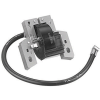
That primary kill terminal is this spade:


Now, with that kill terminal open circuited there is no current in the primary. But the engine runs.
Is then, the magnet induction picked only by the secondary coil ? There is no transformer action from primary to secondary ?
With that kill terminal grounded, there is current in the primary when the magnet passes by. Then, if there is current, there should be transformation from primary to secondary for spark to be created. But the engine stops.
Some light, please ?
OK; about 110V peak unloaded.
These schematics shows that when the primary is grounded/shorted by the switch, the engine turns off, as the passing flywheel magnet 1 does not produce spark in that condition. Primary and secondary are not in parallel.


That primary kill terminal is this spade:


Now, with that kill terminal open circuited there is no current in the primary. But the engine runs.
Is then, the magnet induction picked only by the secondary coil ? There is no transformer action from primary to secondary ?
With that kill terminal grounded, there is current in the primary when the magnet passes by. Then, if there is current, there should be transformation from primary to secondary for spark to be created. But the engine stops.
Some light, please ?
Last edited:
A transformer has a primary winding which generates a magnetic field in the iron core and this is coupled to the the secondary. The output voltage is proportional to the ratio of the turns.
In this case, the magnetic field is produced by the passing magnet. The voltage is generated in the two windings in proportion to the number of turns. Shorting one winding forces zero volts on the other winding - engine stopped.
In this case, the magnetic field is produced by the passing magnet. The voltage is generated in the two windings in proportion to the number of turns. Shorting one winding forces zero volts on the other winding - engine stopped.
...Shorting one winding forces zero volts on the other winding...
OK. That is the key !
There will have to be a method of opening the winding at the critical time to get the spark. In the early car days, the contacts were opened in the cylinder and an arc was drawn at low voltage. Later a set of points were opened in the primary of a transformer to induce a large voltage on the plug in the cylinder.
In this case @debe says that there is an electronic module in a B&S engine to do this. The energy in the inductance is then diverted to the spark.
In this case @debe says that there is an electronic module in a B&S engine to do this. The energy in the inductance is then diverted to the spark.
Sorry to dig about in this post as it is a bit off topic. I am looking to sense the primary side with resistor/transistor setup. I've had some success using arduino but the signal seems to be messy. Going on the values captured by bebe with the scope, is there any advice for a circuit i could implement to capture the signal cleanly. I had tried implementing ceramic caps (various values 10n -100n) but it only seemed to clean up on lower rpm but as soon as it hit over 1500 rpm it got messy again and missed out pulses.
A
A
- Status
- Not open for further replies.
Similar threads
- Replies
- 2
- Views
- 2K
- Replies
- 3
- Views
- 2K
- Replies
- 1
- Views
- 783


