Maker Pro
Maker Pro

LTSPICE Help needed to make transformer coupled amplifier & push pull amplifier

Can you please help me to simulate this two circuits? I tried many times but failed.
 

Attachments

  • 1.PNG
    1.PNG
    239 KB · Views: 403
  • 2.PNG
    2.PNG
    276.8 KB · Views: 288

Harald Kapp

Moderator
Moderator
A good start is drawing these circuits in LTSPICE and showing us the resulting circuits. You may also upload the .asc files so we can have a detailed look at them.

What kind of project is this? Homework or an assignment? It looks like.
 
For your kind information, I have uploaded my LTspice file what I did..... couldn't do finishing.
 

Attachments

  • Push-Pull Amplifier.asc
    2 KB · Views: 129

Harald Kapp

Moderator
Moderator
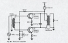
You need to add a statement that defines the coupling between the inductances.
The general form of the statement is
K L1 L2 factor
where L1, L2 are the two inductances to be coupled, factor is the coupling factor. For an ideal transformer factor=1, but a real transformer has losses so factor <1, e.g. 0.95, To get the simulation up and running factor=1 (although not realistic) can be used.

You also need to assign values to all components. R4=R wil not work, C1=C will not work either.

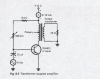
R5, C2 can be omitted since you don't have the 18 kΩ resistor on the transformer's center tap. It seems to be optional as the conenction is dotted in the original schematic.

You have no power supply. The 12 V ned to go to teh center tap of the output transformer. You therefore wil have to split L2 into two inductors L2a, L2b and add the 12 V to the center tap. You will also need to add a coupling factor 'K' for L2a and L2b as these are in the same core.

And again: is this an assignment, homework or similar?
 

hevans1944

Hop - AC8NS
Your LTSpice schematic doesn't look anything like the schematic you posted earlier. Edit the LTSpice schematic and try again. You might want to visit some of the links at this Google result page.

As Harald has already asked (twice now): is this a school assignment, homework, or are you just trying to learn on your own from a text book?
 
Thank you for your reply. Actually Its a Lab Assignment. No one could solve this problem in our class in LTSpice. That's why I'm trying to solve it.
 

Harald Kapp

Moderator
Moderator
You'll also have to split L3 into 2 inductors, add mutual inductance (coupling factor K) and the 18 kΩ resistor to 12 V as well as the connection to R5 and C2.
Also give the inductors some series resistance
upload_2016-12-12_9-45-33.png
The exact value of the series resistance is not critical (you haven't been given that information on the original schematic anyway). I used 10 Ω, this makes LTSPICE happy - otherwise it will complain about shorted voltage sources and such as ideal inductor has 0 Ω resistance.
 
Can you please check my circuit in LTSPICE. Its 2nd circuit. Here is attached file
 

Attachments

  • Draft3.asc
    2.6 KB · Views: 77

Harald Kapp

Moderator
Moderator
Visually the schematic lookes o.k., but as you will have noticed it doesn't simulate. You need to add some series resistance to the inductors, see my post #7.
 
See now...what should I do..??..:( :( How can i connect (0-100) mA?
 

Attachments

  • Draft3.asc
    2.8 KB · Views: 68
  • pp.jpg
    pp.jpg
    34.4 KB · Views: 155
Last edited:

Harald Kapp

Moderator
Moderator
  1. Your 12 V source is reverse. Connect - to ground, +12 V to the center taps of the coils.
  2. How i connect (0-100) mA?
    this is simply an ampere meter. You don't need this for the simulation. You can simply measure the current through the 12 V source using the LTSPICE current probe.

And you still have no series resistance in the inductors!
 
Now, I got simulation. Thank you very much..:) Is it okay? What do you think about selection of the value of inductance of my circuit? Do you have more suggestion to make it perfect?
 

Attachments

  • Draft3.asc
    2.8 KB · Views: 65

Harald Kapp

Moderator
Moderator
Now, I got simulation.
I wonder how. Your voltage source V2 is still in reverse polarity. You need +12 V at the center tap of the right transformer and the 18 kΩ resistor.
Dont get confused by the + and - signs on the ammeter in your original schematic. That's the polarity of the ammeter, not of the voltage source.

What do you think about selection of the value of inductance of my circuit?
I'm sorry, I have no idea which inductances shall be used. There is no information on these values in the original schematic, not even the transformer ratio is given. When assigning inductance values to model a transformer ratio, note that the inductance ratio is proportional to the ratio of windings squared:
L1/L2 = N1²/N2²
 
Why are you simulating an antique circuit? Philips made a similar transistor amplifier in 1955 (61 years ago) using a transformer:
 

Attachments

  • Philips transistor amp-1955.PNG
    Philips transistor amp-1955.PNG
    186.7 KB · Views: 153
Now, I got simulation. Thank you very much..:) Is it okay? What do you think about selection of the value of inductance of my circuit? Do you have more suggestion to make it perfect?

Is it okay now? I connected +12v across center tap & 18k as you said
 

Attachments

  • Draft3.asc
    2.8 KB · Views: 65

Harald Kapp

Moderator
Moderator
The '-' pole of the power supply (12 V) goes to ground (that little triangle symbol.
Is it okay now? I connected +12v across center tap & 18k as you said
I didn't say that as you'll discover when you read my post #13.

It's still wrong, sorry. Have a look at the original circuit. +12V goes to:
- the 18 k resistor (R5, that one you got right)
- the center tap of the right transformer (L4, L5, you got that one wrong by connecting the '-' pole of the 12 V source here)
 

Harald Kapp

Moderator
Moderator
No, it is not correct. By simply reversing the voltage source you now have +12 V on the right transformer's tap (L4, L5) and 0V ('-' pole of the 12 V source) on R18.
This is not what I stated:
You need +12 V at the center tap of the right transformer and the 18 kΩ resistor.
(emphasis added)..
For the other side of the power supply I wrote:
The '-' pole of the power supply (12 V) goes to ground (that little triangle symbol.
 

Harald Kapp

Moderator
Moderator
O.K., I'm not a native speaker but generally I can express myself in English quite a bit. As the saying goes: A picture is worth a thousand words:
upload_2016-12-13_11-0-45.png
 
Top