Maker Pro
Maker Pro

LM317T and how it works

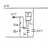
I just came back from Radio Shack with a LM317T voltage regulator.

I have a question. I'm going to use this for my car- I need 5.5 volts for a sensor I am adding. My question is, the battery 12V going to the LM317T will not be constant- the alternator goes up to 14V, and the actual DC voltage from the battery will vary quite a lot. With variable input voltage, will the output voltage vary as well, or will it stay constant?

Thanks.
 
Last edited:
You can look up the data for the LM317T. I would expect that the output would not vary more than a mV or so with the input range you have.
You will get a little variation in voltage if the current varies, perhaps another mV.

So, is the answer to your question Yes or No?

Make sure that you have the recommended capacitors at input and output to ensure stability.
 
Well, it wouldn't be much of a regulator if the voltage changed would it?

Yes, the output voltage stays constant, as long as the input voltage is high enough (about 2-3V above the output)

Bob
 
Well, the reason I ask is because the sensor I am installing, a Manifold Absolute Pressure sensor, does change depending on the input voltage. The signal voltage is 5V from the ECM, and the output is .4V to 4.65V depending on the pressure in the manifold (zero Bar to 2.5 Bar). It does this with a voltage regulator. The pressure diaphragm changes the resistance on the adjustment input of the regulator. But if you increase the voltage in, say to 5.5V going into the regulator, the output will also change. At 5.5V, at 1 bar the output would be about .49V. At 5V, 1 bar would be about .57 volts. So in this case, which is the only case that I've had experience with as far as voltage regulators go, the input voltage drastically affects the regulator's output.
 
I don't know what you know about electronic circuits, but I'm wondering if you know
that a LM317 is and ADJUSTABLE voltage regulator, as opposed to say an LM340T-5 (5 volt fixed), or LM340T-12 (12 volt fixed). You set the LM317 to the voltage you
want with resistor add-ons. From your post, I'm thinking you're considering using the
varying signal voltage from your ECM to control your LM317 output voltage? Which is
probably not what you want. As mentioned in previous posts, check your data sheet.
 
Nope.

What I did was put a 1000ohm 15 turn variable resistor on the LM317T. I'm putting battery voltage to the regulator (which is the reason for the post, battery voltage varies) to get 5.5V output. I'm tricking the MAP sensor to produce the same signal as a 2 bar sensor. I use HPTuners to tune my car (I added a supercharger to the engine), and my custom OS can't see the top of the range of a 2.5 bar MAP sensor, which is what came with the supercharger.

But, I'm having an issue. It will only dial down to 10.2V, and then it drops to millivolts, which I'm guessing is actually zero or near zero. If I turn the resistor clockwise, the voltage increases. So do I need to add a resistor to the ground to get it to go lower? The heatsink when the voltage drops off gets VERY hot, so it's obviously turning the entire battery voltage into heat, right?

I'll try to draw my circuit so you all can better critique it.

MAP_schematic.JPG
 
Well, I think I figured out my problem... I think I wired the regulator backwards... I think I have the ground on the supply side and the 12V on the ground side. I probably burnt the thing up (though it is still giving voltage out the center post somehow).
 
This should give slightly under 5V out.
The temperature will depend on the load current.

A buck regulator may give more problems if is is noisy.
 

Attachments

  • c131frdave.png
    c131frdave.png
    2.9 KB · Views: 126
Thanks Duke. If I wanted 5.5 volts, would I put the pot where the 560 ohm resister is?

Load current is supposed to be less than half an amp according to the spec sheet.
 

(*steve*)

¡sǝpodᴉʇuɐ ǝɥʇ ɹɐǝɥd
Moderator
Yep, you place the pot where you indicate.

Note that the LM317 will need a heatsink, and the tab needs to be insulated so it doesn't short out to anything.

If the LM317 gets too hot it will shut down.
 
Your circuit diagram was correct. If you can set your 1000 ohms to 750 ohms. You should have 5.51V as output.

Can you post picture of LM317 and connecting wire. Pls label wire for
Input, Output and Adjust wires. There might something you missed.:)
 
Being a relative newb, I recently made my first circuit with a lm317. I must admit it was wired backwards for my first attempts, and I also burned out a potentiometer. It was worth the efforts though. Use an online lm317 calculator to get the combination of resistors for the voltage you require. I would not worry about the voltage fluctuations after you get it working. Flucuations would be in the one/one-hundredth volt to millivolt range if at all.
 
Thanks everyone! . I very much appreciate all the replies!


Here are some pics of my monstrosity. My soldering is crap, but I checked it with the Fluke and the joints are open to each other. You guys think my iron is too hot? It's a crap 25W Walmart special.

The soldering side is labeled. "Term" refers to the pins coming out the regulator.

.
 

Attachments

  • regulator.jpg
    regulator.jpg
    93.2 KB · Views: 92
  • solder.jpg
    solder.jpg
    132.7 KB · Views: 135
Last edited:
The excess solder on the side is where I dragged my iron on the edge while talking to my 5 year old. It wasn't connected to anything, so I let it go.

I just measured the resistance between ground and output joints and got infinity. I measured between the supply pin and the output pin and got 1.2 mOhm. Shouldn't the ground and output measure 220ohm since there is a 220 ohm resistor there? I think I messed up...
 
Last edited:
I just noticed on the LM317T calculator page that the tab where the screw goes through it is labeled as Vout. Is that true? If so, my board is shorted...
 
Top