All of the inputs to the dual D-type flip-flop, SN74HC74,
must be CMOS level inputs: -0.5 V < Vi < (Vcc+0.5) V
For a 5 VDC supply this generally means all inputs must be between ground and +5V.
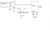
The easiest way to guarantee this with ±12 VDC outputs from your UA741 op-amp (which is NOT a comparator) is to apply a "catch" diode for positive outputs and a "clamp" diode for negative outputs.
For the "catch" diode, its cathode is connected to +5 Vcc, its anode is connected to CMOS input terminal, and the output of UA741 is connected through a 10 kΩ resistor to the CMOS input. The "catch" diode will conduct when the UA741 output exceeds +5 V plus the foward voltage drop of the "catch" diode. Also required is a "clamp" diode with its cathode connected to the CMOS input and its anode connected to the SN74HC74 common or ground. The "clamp" diode will conduct to prevent negative UA741 outputs greater than one diode forward voltage drop from being applied to the CMOS input.
This combination of a 10 kΩ current-limiting resistor and two diodes must be applied at every CMOS input subject to ±12 VDC voltage swings. Small-signal diodes are recommended, although general-purpose power diodes will work if the level transitions are not too fast.
The active-low CLEAR (RD) and SET (SD) inputs of the SN74HC74 are level-triggered NOT edge-triggered inputs. Design accordingly.
Edit:
@(*steve*) beat me to it. Schottky diodes are good. Wish I had one of those nifty schematic drawing programs. <sigh>