While waiting for the thyristors....

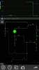
I built this, simulator says it works (using a 2n222 (generic npn) and a 2n44?? (Generic pnp)
In real life, it fails to work...
After an hour or so i gave up and tried the above circuit (simply moved the feedback point to the base of the npn)
This works, but i don't understand why the first circuit fails (if you get some free time, give it a try)
It's a self latching circuit, touch gnd via the 1k on the npn it goes off, supply a pulse of vcc, the LED comes on, basicslly a thyristor... it has me stumped as to why the first circuit fails but works on a simulator :/
")