Maker Pro
Maker Pro

Kenwood KR-8050. A+B Speaker selection not working.

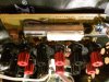
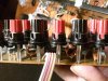
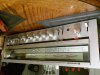
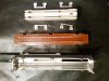
A, B and C channels work, but when selected for A and B channels to work together, there is no sound, not even static. Do these switches go bad inside?
 

Attachments

  • 20141219_173408.jpg
    20141219_173408.jpg
    166 KB · Views: 266
  • 20141219_173649.jpg
    20141219_173649.jpg
    169.3 KB · Views: 289
  • 20141219_173710.jpg
    20141219_173710.jpg
    199.2 KB · Views: 283
  • 20141219_173724.jpg
    20141219_173724.jpg
    184 KB · Views: 259

KrisBlueNZ

Sadly passed away in 2015
I guess it must be, unless there are some really bad dry joints on the switch pins or broken tracks on the PCB. I would try carefully removing it and opening it up. The problem may be obvious.
 
Yeah, I was thinking about opening it up but i wonder if its fixable though. Im not sure if i could find one like this at a parts store lol.
 

KrisBlueNZ

Sadly passed away in 2015
Yeah, I doubt you would find a replacement. That's why I suggested that you remove it and open it up. I think the problem will be obvious. You might or might not be able to fix it, but you should be able to get it back to its current state.

Do you use all three speaker output sets? Do you want one set always ON? Perhaps you could change the wiring on the PCB so that you don't need to use the A+B+C position?
 
Its my brothers receiver. I just wanted the selector to work just incase he wanted to run 4 speakers at the same time. Im gonna open it it up and see if i can see anything
 
Before i remove the switch, i was gonna ask you something. It has resistors and capacitors on the board, and two coils. Is it possible one of them went bad and isnt letting the A+B to work when selected? All A,B and C channels work when selected separately.

20141220_024919.jpg I posted a pic of the speaker selections
 

KrisBlueNZ

Sadly passed away in 2015
No, that's not possible. Those components connect between the amplifier outputs and the switching, so if they failed, they would affect all speaker outputs.

Here's the schematic of the speaker switching section.
speaker switching.png

The G, L, G and R connections at top left are from the amplifier's speaker outputs. There are two grounds; one is used for the left speakers and the other is used for the right speakers.
 
Everything seems to looks ok inside the switch. Anything else i should look for before i put it back together?
 

Attachments

  • 20141220_070959.jpg
    20141220_070959.jpg
    218.7 KB · Views: 195
  • 20141221_000131.jpg
    20141221_000131.jpg
    204.5 KB · Views: 164

KrisBlueNZ

Sadly passed away in 2015
You can check for the correct continuity patterns in all positions of the switch. There's not enough information on the schematic for me to write up a checklist, but you may be able to figure out which pins are supposed to have continuity in each position by looking at the diagram of the switch in post #7 and matching that up with your memory of how the switch was constructed internally.

It looks like on each position you should have four independent continuity paths, and the pin layout on the diagram should match the actual pin layout on the switch.
 
Are you testing the A+B switch position with speakers connected to A an B at the same time? In the A+B position, speakers A and B are wired in series, so both must have speakers connected to work. You can't test one at a time.
 
So they are! Good catch.
Thank you. All consumer amplifiers operate in this way, as putting 2 sets of speakers in parallel could easily put too much load on the output section, causing overheating and shutdowns. I have a feeling that nothing was ever wrong with that receiver and the time spent was a lesson learned...
 
Top