Maker Pro
Maker Pro

Is there a name for this type of motor ?

A kitchen mixer in the sixties had a variable mechanical speed control that changed the angle of the stator brushes by sliding a lever.
Tried to fix it as a kid when failed but did not understand how it worked. And still not. So, decided to ask now, just for curiosity.
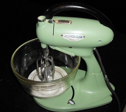
Found a picture, here it goes :

600c6e12c20384b179c04d7521dceb03.jpg

Sliding the chrome knob down in its slit, showed 'beat' 'whip' 'slow' ... labels behind a window. No triacs inside.
 
Most likely a Universal motor, it will run on AC or DC, some had a electromechanical switch mechanism that would open and close to regulate the rpm.
Another similar AC motor is a variable reluctance motor, which it is possible for it to be.
Modern ones have a Triac type controller.
I think you mean armature brushes?
M.
 
The kitchen aid is the reference I made to the electro mechanical type, but the OP mentions changing angle of brushes?
M.
 
Thanks.
I believe am saying it right, stator brushes. Of course they contact the rotor.

But not very static/fixed either. The brushes assembly mounted on a movable plate able to be rotated by the speed lever. Continuously variable; no steps, no winding taps. Zero electronics inside, no potentiometers, rheostats... At the top end of the lever linear travel, a cam opens points to turn off.

Yes, should be an universal motor, but the position of the brushes was adjustable in angle to vary the speed. The image in post 1 is for an identical mixer (Hamilton Beach)

upload_2018-3-15_17-48-9.png
See the brushes at "12:00 and 6:00" ? The brushes were mounted on a plate capable of rotating 90 degrees, to the point of imagine them turned up to "3:00 and 9:00" The speed control lever mechanically and directly attached to the brushes mount plate.

The speed indicator window is shown at
----> https://www.ebay.ca/itm/Vintage-Ham...257097?hash=item3ae0c73e09:g:eZEAAOSw53NY91PB

Found referenced as being since the 1930's !
This similar model has no window; instead, labels on the body, perhaps with detents:
Vtg-Chrome-Hamilton-Beach-Mixer-w-Beaters.jpg
 
Last edited:
Older windscreen wiper two speed motors have brushes at different angles, A universal or DC motor runs at slow speed when the stator is at high voltage and will run at higher speed when the field is weakened. The field is presumably taken from the brushes which will have different voltages at different angles.
 
Thanks. Does that type of controllable universal motor have a 'name' or description ?

Here is one running ---->

An a guy butchering one between time stamp 7:00 and 9:00
---->
 

Eyyyyyyyy Hombre . . . . . . ¿ Que Paaaaaaaaaaaaaaaaaasa ?


Considering that yo MaMa's Hamilton Meach Bixer . . .ooops Lys-dexia kickin' 'n again . . . . Beach Mixer was the G series, and I see NO reason from deviation from a PROVEN workhouse model for decades . . . .until they started toying with solid state innovations and their incorporations .

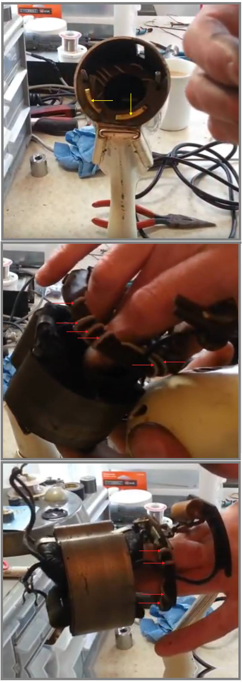
Ignoring of the smoke and mirrors, variable phase angle shift with a rotating brush holder, instead, fully expect to find that the speed shift tab ties into a rotary bakelite disc that moves its pressure contact to meet with the two contact tabs shown on the top photo.Then, there is the direct connection for full speed operation.
A common series AC/DC motor is run at full voltage for high speed or thru two series asbestos insulated nichrome wire resistors for the two slower speeds, as are engaged by the two contacts shown.

The given reference to the HAMILTON BEACH SODA MIXER model finds it using an inductor with two taps instead of the RESISTORS used in yours. The line AC passing thru the inductor's reactance at 60~ equates to series inductive reactance to drop the voltage just as your resistors did.

I still have and can use the hand version of this HB unit (Turqoise color) and it is made the same. I tore it down once for brush replacement . . . they had worn down so far that it stuttered on running speed.
Those units 24 segment rotors are certainly due a cleaning and repolishing to show all pristine fresh rosy copper surfacing again.

And if the end cap solder blob of the paper capacitor / to / foil surfacing by compression / touch proximity has loosened, and is open circuit now, a new generation of like value cap really is in order.
It supresses the back EMF sparking at each rotor segments end contact transition by absorption and the resultant decrease of metal erosion by sparking.

ILLUSTRATIONS . . . . . . . . . . .
  • Speed contacts
  • One nichrome wire resistor element
  • Mate . . . . nichrome wire resistor element
Thaaaaaasit . . . . .. . .

.
FjQrUKf.jpg


73's de Edd
.....
 
Another elaborated response from Edd... thank you, muchacho, for your permanent dedication.

From what I remember... It was only about 50 years ago... :rolleyes: the yellow arrows point to a sliding contact that supply the connection for the movable brushes assembly.
Its solid design with no solid state components has been abandoned by this century by cheap, finite-lived disposable, unserviceable designs -pissed off-:(

Perhaps the nichrome resistor which I did not notice then, keys understanding to its workings. Whenever I can relate that to infinitely variable speed control.

If you see a tutorial for that speed controlling method somewhere, please link.

73 !

----> Did you ever receive a direct message titled "Your contacts" ?
 

hevans1944

Hop - AC8NS
I hate to bump this old thread, but the speed control principle that @Externet described was exactly the same as was used on a motor that my grandfather (a retired, West Virginia, deep coal mine electrician) had in his garage in Tennessee in the 1950s. It worked exactly as you described, varying its speed with the position of the brush assembly as it was rotated (but not very far, nowhere near ±90 degrees) around the rotor axis.

IIRC, it could also be used to reverse the motor, and one had to be careful not to position the brushes exactly between the forward and reverse directions because power applied under those "do not rotate" conditions would damage the motor. I got the impression that this was a "set and forget" adjustment mainly used to set the motor speed (and direction) for a particular load, such as a conveyor belt loaded with mine tailings perhaps. Coal was removed from the mine in small cars that ran on rails, but grandfather never told me what the motive force for the cars was. No doubt some sort of electric motor was involved.

This was a fairly large motor, about the size of a 1 hp induction motor commonly available today. However, it was a brushed AC/DC "universal wound" motor with continuously adjustable brush positions. I am very surprised anyone here at Electronics Point has ever seen one!
 
Those were quite common Many decades ago and consisted of three types, (1) Repulsion-start, Induction-Run (2) The Repulsion Motor (3) Repulsion-Induction motor.
They each have their own characteristics of course.
The movable brush version was to enable reversing of the motor. Some had a brush lifting technique
M.
 
I should have added however, that the three types described, in spite of having brushes were AC induction only.
i.e. Non-Universal.
M.
 

hevans1944

Hop - AC8NS
I wish I had "inherited" Grandfather's motor after he died... I like collecting old "junque" like that... but the thought never occurred to me. I could barely lift it anyway, much less put it to use. I didn't have enough foresight, as a young kid, to try to find and write down the name plate information, but @Minder is probably correct: AC only. I did acquire his "bee smoker" after expressing an interest in it while "the grownups" squabbled over who would get what. Grandfather raised bees in West Virginia and IIRC tried to do the same in Tennessee, but I don't remember any working bee hives in Morristown, where he and my grandmother retired. I like bees and will probably try to raise some here in Florida.

Grandfather demonstrated his motor to me by connecting it to 120 VAC running between his house and the detached cinder-block, one-car, garage with its hard-compacted dirt floor. Real cozy that garage. Rather cold in the winter unless Grandfather warmed it up with an electric heater. Everything in Tennessee in the 1950s ran off of cheap electricity generated by the Tennessee Valley Authority (TVA) hydroelectric dams. Nearby Alcoa (Aluminum Company of America?) consumed massive quantities of electricity in electro-chemically separating aluminum from alumina (Al2O3) extracted from bauxite ore, but there was plenty left over for other commercial uses. Don't know what the situation is today, what with the increase in population and land development, but the dams are still there and the TVA hasn't gone away.
 
Heavy note for all the mechanizm lovers in here.....
As I remember my schooling, the armature on these had two sets of windings, one for the fast speed and one for the slow speed making the connections proper was imperative for the switching positions to be good.... and well the motor turn fast when the switch was in fast and the motor turn slow when the switch was in slow. Connecting one of the resistors to the wrong side caused the motor to overheat tremendously, and melt the armature??? huh woe is me??? howdidthathappen??? dunno, probably a design flaw at the factory...
 
Top