Rooster92,
I concur with the previous posts pointing out the lack of base drive for the power transistor in your original circuit. There are quite a few more potential problems.
I'll try to add to what the previous posts have said.
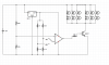
Can you reveal the identity of your op-amp? Looks as if it may be the DIP-14 device on the breadboard in the picture, but I can't quite read the P/N on it.
You should know that not only may this device not be able to fully turn-on the power transistor, it may also be unable to turn it fully off! Some devices can pull the output pin very close to the negative power supply rail, others only within a few volts.
The heatsink in the picture is only good for a few watts, nowhere near 75W. You would need something much larger, perhaps with a fan.
Transistor current and power ratings must be derated in use. The data sheet values are invariably given for 25C at the silicon. The silicon runs much hotter than the heatsink temperature. The datasheets for the transistor and the heatsink will help calculate what to expect, but a reasonable expectation is to run the device at 1/4 to 1/2 the datasheet values.
3055T is an incomplete part number. The 2N3055 is a different part, in a metal can, rated at 15A and 117 W. The "T" suffix usually means a TO-220 style plastic package as seen in the photograph. The 10A & 75W ratings reflect this difference.
None of these parts is much good beyond 4-5A. The gain and saturation voltages degrade as you approach the maximum rated current.
To get a low saturation voltage at several amps collector current, you need to drive the base of most bipolar power transistors at about 10% of the collector current. So you should try to provide about 1A base current for a 10A load.
If you already have a bag full of the plastic 3055T parts, you might parallel 2-4 transistors to drive the lamps, then use one more of these, plus a small signal transistor, to boost the base drive to around 1A, total. You would need to either add small emitter resistors for the output transistors, or divide the lightbulb strings among the transistors' collectors. Separate base resistors will be required, too.
Using multiple power devices helps spread the heat around, and helps keep the devices away from their maximum ratings.
Starting from scratch, I think N-channel power FETs might be easier to use.
If your op-amp output does approach the supply rails, with the 12V supply, you should be able to drive an ordinary power FET directly. No logic-level gate device would be required.
Any of the 60V power FETs mentioned might be made to do your job, particularly if you parallel several devices.
None of the posts so far address what happens as the battery voltage reaches the voltage at which the discharger is to remove the load from the battery ( "threshold voltage" ). You don't say exactly what should happen, here.
The present circuit will attempt to throttle back the transistor to keep the battery voltage at the threshold setting. More than likely, you will get oscillation, instead of a nice steady decrease in current as the battery discharges further. In either case, the transistor will see a lot more power than it would sitting there turned on fully.
Perhaps you want the discharge to end altogether when the threshold voltage is reached under the full load. That is, as soon as the threshold voltage is reached, the load is switched off and stays off. This makes the transistor's situation easier, as it never has to dissipate much power.
Conversely, you might want the discharge current to taper until the open circuit voltage of the battery is below the threshold voltage.
Depending on how you want the circuit to behave, parts can be added around the op-amp ether to calm any oscillations while throttling-back the load current, or to make the current to go to zero and stay there, once the threshold voltage is reached.
If the transistors are to throttle the discharge current, you will need to arrange for them to dissipate lots of power. Multiple transistors in parallel is a good idea. A resistor bank to share the dissipation is, as well.
Lightbulbs are not the best answer for your load bank if the current is to be throttled. Their resistance rises as they see more voltage. One would prefer something with a resistance that falls with rising voltage, in order to reduce the power that the transistors have to dissipate.
Depending on the battery's capacity, and on how long the set-up may go unattended, you might want to add a circuit to turn the discharger completely off, once its job is done. The control circuit will continue to discharge the battery slowly, even with the power transistors fully off.
One more thing: the 7812 may oscillate without an input capacitor. A 10uF 35V electrolytic should calm it down.
Ted

")