The precision rectifier is
described here.
I combined two effects:
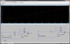
Offsetting the threshold for the diode circuit by adding -100mV to the + input of the opamp plus adding -300mV to the input voltage via R1 and R3.
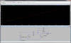
You can replace V2,R1 plus V1,R3 by a voltage source V=(V1+V1)/2 and a resistance R=R1||R3=5K. The gain of the ideal diode wil be g=-R2/R=-2. I'll add an image for reference.
Assume Vin=V2=-200mV. Then (V1+V2)/2 = -250mV. This s negative compared to V3, therefore the output of the opamp will be positive. D1 will be off and D2 will close the feedback path around the opamp such that at the inputs of the opamp V(-)-V(+)=0V. As long as there is no load at the output (!) R2 will show the -100mV that are present at the - input of the opamp at the output.
Note that if you add a load resistor that is noteably smaller than e.g. 100kOhm, you will see a drop in output voltage. This is why Kris asked for more details about your requirements. The inverter you'll have to add for a positive output voltage needs to have a very high impedance. It is best to insert a noninverting buffer at the output of the ideal diode circuit to minimize the load.
Assume Vin=V2=+100mV. Then (V1+V2)/2 = --100mV. This is the same voltage as V3. The output of the opamp will be 0V (ideally, in practice it will be either >0V or <0V, depending on tolerances). D1 will still be off and the above explanation for the output voltage applies.
Assume Vin=V2 >100mV, e.g. Vin=1.5V -> (Vin+V2)/2=0.6V. This is positive with respect to V3 and the output of the opamp will go positive. The feedback loop is closed via R2 such that the output voltage is Vout= [(Vin+V2)/2-V3]*2-2*V3 = [0.6V-(-0.1V)]*2-(-0,1V)=0.7V*2+0,1V= 1.5V
By mixing the two effects it is not very easy to understand the circuit - put possible.