Maker Pro
Maker Pro

how to find out current in each resistors

Hello
I have multimeter, breadboard and some resistors. I can connect resistors on breadboard
I want to do some real work. I can measure voltage , current and resistance with multimeter. I have different value of resistors
If we know two known value than we can find one unknown value ie. if we know voltage and resistance we can determine current by ohms law
equivalent resistance = 3.28 ohms
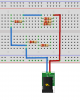
look both Images
1. Is the connection on breadboard as same as show in schematic ?

I don't understand how to find out current through the 3 ohms , 4ohms and 5 ohms resistors
 

Attachments

  • IMG_20151018_134155_1.jpg
    IMG_20151018_134155_1.jpg
    17.1 KB · Views: 134
  • network.png
    network.png
    106.3 KB · Views: 134
Last edited by a moderator:
Calculate the total resistance of the 3 resistors. multiply by the current. this is the voltage across them. I = V/R for each resistor.Don't forget the .1Ω when calculating the current
 
Last edited:
I am a little confused as to how someone with 274 posts over nearly four years on this forum is unable to work out this simple series/parallel resistor circuit, and can't see the errors in the breadboard.
 
I am a little confused as to how someone with 274 posts over nearly four years on this forum is unable to work out this simple series/parallel resistor circuit, and can't see the errors in the breadboard.
Hello Kiwi
I try to clear your confusen I thing my title selection was wrong. It should be theory vs practical
why I am on this forum
: because I don't understand electronics easily

do you think that all peoples have same capability to learn ?

if you will read the top 5 lines of my post. you will see that I want to do some practicals to know real facts that's why I posted breadboard image. I know series / parallel resistor on pages. I never tried on pcb or breadboard using multimeter

I can solve the simple ,series / parallel circuit problem but I am trying to solve complex circuit. I have lot of doubt but I started with small one. I know the answer. I am not good in English . may be reason that I am not explaining in good way

I always see many peoples are very good in theory but when time to prove practically. they don't know anything. I want to be a good in both theory and practical. so that's why I posted simple question
 
Last edited:
Hi Vead,
My math is a complete fail. But you can't measure anything on your bread board connected like that!
Try this in my (badly edited) Paint picture. ( there's a much better version ;) ;) )


network1.GIF


(mod edited image)
 
Last edited by a moderator:
I apologize for wrong title selection and post
I will make some real connection on breadboard ( just learning for concept of circuit theory ) than I will ask you my doubt
thank you very much
 
Hehe, thanks @davenn .
It definitely looks neater. I only left the other resistor there to show the OP there was 6, and only 5 in his schematic.
BTW Dave, what software is it? I might have to get it..

Never mind Dave, I just found it..:)

Martin
 
Last edited:
Top