Maker Pro
Maker Pro

How do you implement a transformer load with a transistor?

Hello everybody, i hope you can help me with a big problem of mine. I need help figuring out how to be able to setup a transistor output with a setup Transformer and get a clean stepped up signal on the secondary coil. For this circuit i will be using signals any where from 1Khz to 100Khz. I will be supplying the transistor with the frequency to superimpose on a 12v DC battery with the transformer connected as a load on the (Collector or Drain; depends on whether its a BJT or MOSFET) lead of the transistor.
I tend to run into more problems at higher frequencies but all in all i can't get a clean signal regardless.Any and all help would be appreciated.
 

(*steve*)

¡sǝpodᴉʇuɐ ǝɥʇ ɹɐǝɥd
Moderator
Well, firstly, it's only the AC component that will transfer from one side of the transformer to the other.

Secondly, if you are using a mains transformer (designed for 50/60Hz) then odd things will happen as the frequency increases. The distortion you see may be related to this.

Also, what is the source of the input signal? Is it a pure sine wave? What is the DC component? You may be partially saturating the core, or the waveform may have high frequency components.

I think you're using the transistor on the primary? Maybe to switch the DC to drive the transformer?

If so, you almost certainly need more than a single transistor because supplying pulsed DC to the transformer is not the same as supplying AC to it.
 
I am using a pulse transformer. I am using a pll ic connected to a BJT transistor with a 10k resistor between. The dc component is just the 12 battery on the collector of the BJT. I am using the transistor to switch off and on the 12vdc to create an pulsed dc signal to be stepped up by the transformer. How could I approiately get a pulsed dc signal across a transformer that is clean?
 

(*steve*)

¡sǝpodᴉʇuɐ ǝɥʇ ɹɐǝɥd
Moderator
I am using a pulse transformer. I am using a pll ic connected to a BJT transistor with a 10k resistor between. The dc component is just the 12 battery on the collector of the BJT. I am using the transistor to switch off and on the 12vdc to create an pulsed dc signal to be stepped up by the transformer. How could I approiately get a pulsed dc signal across a transformer that is clean?

If you're using a pulse transformer, you should not expect that the waveform on the secondary like anything like the waveform on the primary.

As you apply a voltage to the primary, you'll get current increasing. This will result in a voltage appearing on the secondary. As you turn off the transistor, the current through the primary will stop and the energy stored in the core will be dumped, producing a massive spike on the secondary (as well as a large one on the primary).

These transformers are not used in a way where the secondary waveform is related to the primary -- it's all about the voltage spike as the magnetic field collapses.
 

KrisBlueNZ

Sadly passed away in 2015
Stating the obvious... can you post a schematic? And details of the transformer you're using (part number, or winding details)
 
So then what would be the best transformer to use for what I want? What would be the best setup to accomplish my goal? I have included a schematic and part numbers for detailed analysis. I have changed the circuit up a bit but I think it will work this way but haven't had chance to check it out yet since I am lacking parts. I have only simulated it in Multisim.
 

Attachments

  • image.jpg
    image.jpg
    146.8 KB · Views: 170
Transformer details

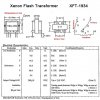
Here is the pulse transformer data sheet. I had to put it in a seperate reply because it wouldn't load with the schematic.
 

Attachments

  • image.jpg
    image.jpg
    75.6 KB · Views: 182

(*steve*)

¡sǝpodᴉʇuɐ ǝɥʇ ɹɐǝɥd
Moderator
So then what would be the best transformer to use for what I want? What would be the best setup to accomplish my goal?

If you could tell us exactly what you're trying to achieve, it would ease the load on our crystal balls.
 

KrisBlueNZ

Sadly passed away in 2015
Part of your problem may be the diode in parallel with the primary. The 1N400x series are slow diodes, designed for rectifying mains frequency and other slow applications. This will affect the circuit's behaviour at higher frequencies.

Also, the presence of the diode may defeat the purpose of the design, since a pulse transformer is normally used in flyback mode, and in that case, the bottom end of the primary needs to be free to "fly back" above the supply rail. That may not apply with this transformer though, because it seems to be designed for 12V drive.

Finally, if you're using the transformer in direct forward mode (I don't know the proper term), you'll probably need to drive it with a symmetrical waveform with no average DC component to prevent the core from saturating. For example, a bridge driver, or a push-pull output stage with a coupling capacitor. You should use a bridge rectifier on the secondary to make use of both sides of the waveform.

It would help if you describe what you want to do with this circuit. What do you intend to connect to the secondary? Can you show the circuitry that generates the drive signal?
 
Hello everybody, i hope you can help me with a big problem of mine. I need help figuring out how to be able to setup a transistor output with a setup Transformer and get a clean stepped up signal on the secondary coil. For this circuit i will be using signals any where from 1Khz to 100Khz. I will be supplying the transistor with the frequency to superimpose on a 12v DC battery with the transformer connected as a load on the (Collector or Drain; depends on whether its a BJT or MOSFET) lead of the transistor.
I tend to run into more problems at higher frequencies but all in all i can't get a clean signal regardless.Any and all help would be appreciated.

The intended operation is in the paragraph above. The drive signal is coming from a PLL as I stated before. The input to the transistor is a square wave. The output from the transformer is going to be a stepped up sine wave of the same frequency. The load will be of no consern at this moment. All I want to know is, if any of you people on this forum know how to build a circuit that will essencely turn a variable frequency dc signal from a PLL( since it never crosses over a 0v reference line) feed to a transistor which will correspond will the signal. This way the transistor will turn on and off the 12v dc battery creating a 12v signal equalizent to the input frequency.
 

KrisBlueNZ

Sadly passed away in 2015
The load will be of no consern at this moment.
Seriously? You don't really know what you're doing, you're asking for expert help, but you KNOW that it doesn't matter what the load is, and you know that there's no need to explain the overall purpose of your design?

If you want help, and some kind of useful responses, explain your project in detail, and provide a complete schematic. And while you're at it, you could address all of the points I raised in my previous post.

Man, krisbluenz your a real ray of sun shine. Did your mother ever tell you if you don't have anything good to say, to not say anything at all. You have been of no real help so far while Steve has at least been trying to help. I said the load is of no concern " at this moment". I didn't say the load didn't matter. I just want to be able to get a clean signal first then apply the load. By the way if you don't want to help then quit replying. I have stated my design very well in the aspect in which any real electronics major could make something out of. I came to this forum for support and help because I tried several different ways of making the circuit and couldn't get the result I wanted. If your confused by the PLL input it stands for Phase Lock Loop which is getting controlled by a 555 timer for simplicity and it can range from 1khz -100khz.
 

KrisBlueNZ

Sadly passed away in 2015
You have been of no real help so far while Steve has at least been trying to help.
I HAVE tried to help. Re-read and try to understand post #9 on this thread. And if you like, respond to it.
Otherwise... well I guess you'd better try that thronomister then.
BTW I know very well what a PLL is. I believe I am well-qualified to judge what is an adequate description of a project, and your posts so far come nowhere near it.
 
Last edited:
Top