Maker Pro
Maker Pro

Help with work to finish my college. Help me please!

Hi friends, I'm about to present my College Final Paper. I carried out this project but I'm not getting the result. Proteus reports that there is a saturation current but I can't get the source (on errors). I have 10 days to finish. can anybody help me? I will attach the Proteus.

ps: there is a lack of connection in one of the transistors but even turning it on, it doesn't work.


Class D Amplifier, 100w


Thanks my friends!!!
 

Attachments

  • AMP-OP_TCC.zip
    18.3 KB · Views: 8
How about a schematic of your circuit for us?
Thanks my friend!
Sorry for not attaching but I was on my cell phone, without the correct image. Attached is the schematic and components.
Resistor 1/4th Watt (39R, 390R, 1k, 1.5k, 4.7k, 15k, 22k, 33k, 47k, 150k) – 1nos.

330R Resistor 1/4th Watt – 3 pcs
10R Resistor 10 Watt
0.33R – 7 Watt – 2 pcs
0.22R – 10 Watt
100nF 100V capacitor 2 pcs
47uF 100V Capacitor
470pF 100V
470nF 63V
10pF 100V
1n4002 Diode
IRFP244
IRF9240
MJE350
MJE340
BC546 – 2 pcs
MPSA43 – 3 pcs

Thanks for the help, this is very important to me.

Hugs
 

Attachments

  • AMP-OP_TCC error.jpg
    AMP-OP_TCC error.jpg
    497.7 KB · Views: 13
  • AMP-OP_TCC.jpg
    AMP-OP_TCC.jpg
    513.2 KB · Views: 12
Hello,

It does not look like a Class D amplifier.
Where is the oscillator and comperator for the PWM signal?

I see two current sources in your schematic.
They are build around Q3, Q4 and Q5,Q6.
The configurations seem to be incorrect:
https://www.merghart.com/p/27/Two-Transistor-laser-current-source

Also have a look at this page about amplifier classes:
http://www.bcae1.com/ampclass.htm

Bertus
Thanks for the reply my friend. I ended up getting this circuit from this site: https://circuitdigest.com/electronic-circuits/100w-power-amplifier-circuit-using-mosfet

To be honest, I'm looking for help because I'm late in college and I might miss my entire course.
So I replicated this amplifier from the site. I apologize for coming to get help without so much knowledge, but I went through some difficult times in my college (depression) and I delayed the course by 8 years... I'm without much knowledge and desperate for the presentation (10 days). Can you help me fix these problems?

Thanks!
 
Hello,

What would you learn from copying a circuit?
Have a look at your Q7.

Bertus
Thank you friend. Excuse me, but I find myself in a difficult and extremely urgent situation. I had severe depression in the past 6 months and therefore had to copy. Thank you for your support. I'll look at the Q7. Thank you and God bless you!
 
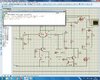
It is a class AB and there is a lot wrong with the circuit as presented.

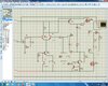
1) the output end of C1 is connected to ground and should be going to the base of Q1.

2) Dispense with R1 and C2.

3) The junction of Q1 and R3 is connected to the positive supply. Remove this connection.

4) The base of Q7 is connected to the positive supply. Remove this connection. Connect the base of Q7 to the junction of Q1 and R3. Q7 emitter should now be connected to the positive supply and nowhere else.

5) The R4 end of R7 should go straight to the base of Q2 and nowhere else.

6) D1 is not needed. Connect the top end of R9 to the Collector of Q7.

7) Connect C5 in parallel with R9 and discard R8.

8) The end of R7 connected to the junction of R13 and R14 should go there and nowhere else. (Breaks its connection to R9).

9) The gaggle of resistors and capacitor, R16, 17 and 18 plus C6 on the output, look as though they are trying to represent a speaker load. Replace them with an 8 ohm resistor to ground.

10) A capacitor, generally called a "Miller Capacitor" (after John Milton Miller) is required between the base and emitter of Q7. 100pf is a good place to start.
Its function is to secure loop stability by creating a dominant pole. Without it, you circuit will oscillate.

11) R13 and R14 are not necessary in a MOSFET power amp and can be dispensed with.

The current sources based around Q3,4 and Q5,6 are OK.

It would help enormously if you could include circuit references with your component list.
As your diagrams are not easy to read, I hope that I have got all the circuit references correct.
 
Top