Maker Pro
Maker Pro

Help with synchro sawtooth generator

Hello all

I'm trying to design a sawtooth generator circuit capable of free running and synchro operation. The purpose is to built a transistor scope in the future to replace my homebrew valve oscilloscope.

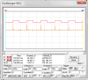
I have designed a circuit capable of synchro operation and I have tested in the protoboard, but this circuit will only generate a sweep, if it receives a synchro pulse. That is suitable for AC, but if I want to measure DC, I guess it will not generate any pulse, or maybe just one at the beginning of measurement.

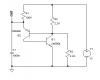
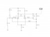
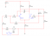
Check the picture to see the circuit I have designed.

How can I build a circuit capable of both sweeps?

I only have bipolar transistors and some FETs.

SN7400 or CD4000 series could also be used.

Thanks in advance

Miguel
 

Attachments

  • Sawtooth.jpg
    Sawtooth.jpg
    95.6 KB · Views: 426
can you use a free running osc? Here is a simple PUT osc I have drawn for you if it's of any help.
Adam
 

Attachments

  • PUT_OSC.PNG
    PUT_OSC.PNG
    4.8 KB · Views: 863
Thank you Arouse1973.

Well, I need an oscillator capable to work both in free running and synchro mode at the same time. When I built my valve oscilloscope, used the circuit shown in the attachment. That circuit, if there is no signal applied from any of the Y-plates (or there is a DC applied), will oscillates at 55Hz (more or less), and when it receive a signal, it will synchronize with it.

I have not been able to do something like that using solid-state devices. That's the circuit in which I need help.
 

Attachments

  • Flip-flop.jpg
    Flip-flop.jpg
    23.8 KB · Views: 300
I don't see any issues with modifying your circuit to work using NPN transistors. You might have to tweak a few values to get it to work. I assume this circuit is your original saw tooth oscillator. Does it have to run on a high voltage to control the CRT? or is this done by another circuit.
Adam
 
I don't see any issues with modifying your circuit to work using NPN transistors.
I tried with N-JFETs on the simulator and it didn't worked. Maybe I have try iy in the protoboard with both nJFETs and NPN BJTs.

I assume this circuit is your original saw tooth oscillator.
Negative. That circuit just provide pulses to trigger the sawtooth generator which in my case is a Miller timebase generator called "Phantastron" or something like that.

Now I'm thinking to use a two level detector on the sweep generator. The lower level will be triggered by the synchro signal and if this trigger pulse does not appear, then a higher level detector will end the sweep. That's the idea, I'm working on it right now. Of course, the triggered sweep will be shorter than the free running sweep, but I guess this doesn't matter if the beam ends outside the visible área of the screen. What do you think?
 
Simulated with 2N3904 NPN transistors. It works!!!! Now to make test on the protoboard.

In the oscillogram it is in red the output of the synchro oscillator and in orange the synch pulses using an RC network

******************************************************************
Is the word "protoboard" OK? or should I say "breadboard"?. We, in Cuba, usually use the word "protoboard", and I thought it was borrowed from English, but I see breadboard on English articles.
 

Attachments

  • Synchro Circuit.png
    Synchro Circuit.png
    15.5 KB · Views: 303
  • trigger oscillogram.png
    trigger oscillogram.png
    25.9 KB · Views: 206
Last edited:
I tried with N-JFETs on the simulator and it didn't worked. Maybe I have try iy in the protoboard with both nJFETs and NPN BJTs.


Negative. That circuit just provide pulses to trigger the sawtooth generator which in my case is a Miller timebase generator called "Phantastron" or something like that.

Now I'm thinking to use a two level detector on the sweep generator. The lower level will be triggered by the synchro signal and if this trigger pulse does not appear, then a higher level detector will end the sweep. That's the idea, I'm working on it right now. Of course, the triggered sweep will be shorter than the free running sweep, but I guess this doesn't matter if the beam ends outside the visible área of the screen. What do you think?

As long as the beam does not spend too much time out of site as this might effect the speed of your sweep for a faster trigger if needed.
Adam
 
Simulated with 2N3904 NPN transistors. It works!!!! Now to make test on the protoboard.

In the oscillogram it is in red the output of the synchro oscillator and in orange the synch pulses using an RC network

******************************************************************
Is the word "protoboard" OK? or should I say "breadboard"?. We, in Cuba, usually use the word "protoboard", and I thought it was borrowed from English, but I see breadboard on English articles.

I use the word strip board for the proto board you solder components to, bread board is the big plastic block thing you poke components in that don't need soldering. Also people call breadboard an SRBP board with just holes and no tracks, but people also call this matrix board. Oh god it's confusing......Don't worry I'll know what you mean.
 
Thanks for your comments.

I mounted the circuit on the breadboard, using BC546 transistors and it worked too, but I noticed a non-predicted behaviour. It gets synchronized with the signal up to 15-18kHz (red trace pulses get narrower as the frequency increases), then the pulses (red trace on the oscillogram) get wider despite increasing frequency up to 50kHz. Not sure if this is due to frequency response of transistors. I will try with faster transistors to see what happen.
 
Top