Maker Pro
Maker Pro

Help with Pot and LM3914

HI there,

I wired a potentiometer between my computer speakers and my sound card to control the volume. I am using a dual variable pot with 500K resistance.

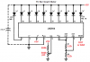
I want to create an official looking volume knob with LEDs that will light up once I turn up the volume. I figured to use LM3914 chip. This is how it looks like in action:

I am not proficient in building circuits and determining correct components. Can someone help with determining the right resistors and components to be used along with 500K pot. My power source is a USB port, 5V.

Thanks in advance
 
Last edited:
The datasheet for the LM3914 shows exactly how to connect it.
The LM3914 is a linear voltmeter. For audio you should use a logarithmic volume control and a logarithmic LM3915 IC that has much more range than a \n LM3914.
 
The datasheet says the maximum input current is 100nA so into your 500k pot the input voltage from the bias current is 100nA x 500k ohms= 0.05V which is almost nothing so the calibration at half pot setting will be accurate.

The datasheet says the max useable input voltage is the power supply (your USB =5V) minus 1.5V which is +3.5V.

Make the reference voltage be =3.5V by using 1.2k from pin 7 to pin 8 and 2.2k from pin 8 to ground. Then the 10th LED will light when the pot is set to maximum with USB +5V feeding 200k resistor in series with the input to the pot.

Connect pin 9 to +5V for BAR mode or leave pin 9 open for dot mode. Use any color of LEDs.
 

Attachments

  • LM3914 with 0V to +5V input.png
    LM3914 with 0V to +5V input.png
    26.1 KB · Views: 143
Oh wow. That's amazing. Thank you very much for that!!

Since I am using a dual pot and it has 2 of input, output and ground, how do I go about connecting it to the circuit?
Also, do I need to use LED's rated at least 3.5V?

Again, thank you very much for your assitance!!
 
Aren't you using a stereo pot as a mono volume control and as a feed to the LM3914 circuit to show the volume setting of the pot?
I showed you how to connect the 500k pot to the LM3914 circuit. Connect the other 500k part of the stereo pot as a volume control.
Since your power supply is only 5V then the LEDs must not be more than 3.5V. The LM3914 feeds them a regulated current that is about 10mA when the circuit uses the resistor values I showed.

You should use an LM3915 and a logarithmic audio-taper pot for a volume control and its indicator circuit. Then it smoothly adjusts volume from very low to maximum. The linear LM3914 and a linear volume control will cram half the rotation into loud sounds (loudest at maximum and still very loud at half rotation) then very quickly drop the level as the pot approaches minimum.
 
I see what you saying. I'm actually using my stereo pot as stereo. I'm using both inputs and outputs. I guess I don't need to be doing that and I just use one parts of the pot.

Thanks as again for your assistance. This cleared up a lot of things
 
You may need to use a signal peak detector to make the display more visible. See Fig 17 of the LM3915 datasheet.
 
What is the function of the LM3914? Instead of showing the levels of the music, don't you simply want to show the setting of the volume control? Then since the audio is stereo that uses a dual volume control (one for each channel) then you need a volume control that has 3 pots in it that is rare to find. Some controls have 4 pots in them for older surround sound.

A DC stereo volume control, tone and balance control IC like an LM1036 could be used but it is obsolete.
 
Top