Sr Pedro Morales . . . . . . . .
Ehhhhhhhhhhh HOMBRE E E E ! . . . . . . . ¿ Que Paaaaaaasssssssa ?
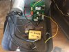
Wasn't sure if that unit was battery powered, what with the pics not even showing a full half of the unit.
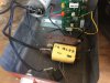
Found a clone that revealed it to be AC powered . . .as per my first pic.
I now have the capability of seeing a power transformer (GREEN ASTERISK) with its two BLACK primary leads coming over to the AC input area with the units AC line fuse and 2 BLUE Transient absorbers.
Its secondary passes thru the case wall and has 3 wires . . .a BL:ACK (common ground) a GREEN (probably a 6-9-or 12 VAC winding for a low voltage for serving the needs of the units transistors and single 8 pin DIP IC) and finally a RED wire which is probably going to be a 120VAC isolated AC output to charge the 20 ufd storage cap which will be used with a sequentially triggered SCR to do a timed dump of its charge into the central YELLOW HV transformer.
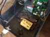
By viewing the 2nd pic you can see the assigned connection / functions of the HV transformer.
Also the units now " loose wires " have been assigned L-W 1 thru 5 labels.
Examine YELLOW ASTERISK, black item and fill me in on construction and connections ? I need more than the pic shows. Is there any soldered connectiion being made to it ?
Here is the way I am seeing this unit :
- LOOSE WIRE 5 needs ~ 160-170volts to charge up, so it goes to that supply connection on the board.
- LOOSE WIRE 1 needs to be grounded in order for the 20ufd cap to charge, so it goes to a ground on the board.
- LOOSE WIRE 2 also needs either a ground or connection to a terminal of the SCR
- LOOSE WIRE 3 relates to the primary of the HV winding, note that on the other side of the transformer, its other companion primary winding lead is going up and terminating at the storage capacitors + terminal.
- Sooooooooooo LOOSE WIRE 3 needs to go to a terminal of the SCR such that when the gate of the SCR is triggered, the SCR shorts this lead to ground and the capacitor then dumps its charge across the HV transformer and a FANTASTICAMACAL high voltage is sent to the fence HOT wire. Then the cap is charging and waiting for the SCR to be triggered, and for the same SHOCK and AWE cycle to be repeated.
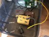
- LOOSE WIRE 4 has been clipped, so see if you can find evidence on the PCB of a wire / its shards, or a YELLOW plastic remnant.
I relate its function as being a sensing loop. The wire passes thru a mounting hole screw in the transformer laminations, and that then will be acting as an almost 1 turn winding on the transformer.
Seeing that 8 pin IC on the board, one would almost want to think of it as being a NE555 for timing the SCR drive pulse.
Instead, I now think that it will be a dual op amp, and is using one section for a pulse soure for SCR gate triggering, unless they are using an Unijunction transistor.
That then leaves the other amp section for an amplifier to take the just referenced sensed input and amplify it and use it as a meter driver via some proper differentiating and hang time circuitry.
With a good spark output, the transformer will give one healthy, long ringing waveform and induce a signal into that sampling winding and it then is amplified to produce an almost peak, pulsed reading on the units frontal meter.
Should the fencing run encounter any leakage to ground on its length, that will load down the high voltage circuitry and
dampen down the inductive ringing and the amplified sample diminishes and the meter reading declines proportionatively.
CAUSE ?
Cattle brushing acrosss the fence?
Tumbleweed blowing into the fence?
Grass / weeds having grown up enough to touch the fence bottom wire.
Hunters crossing the fence
Jr challenging his 3rd grade friend to see who can pee far enough to hit the fence wire, with Jr then having a quite bucolic and lackluster performance, and with friend winning, but all at a surprising and painfull cost.
Ahora . . .Amigo . . . . do you have the techno-savvy to take a Digital Volt-Ohm-Milliameter in hand and in a no power condition, do some OHMS testing, if not, ask for specifics..
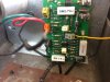
Initially confirm the condition of the two BIG diodes on the board and then the smaller ones.
Then ohm out the 3 large white porcelain power resistors on the bord, strongly suspecting no problem with them.
Looks like 2.7 ohms, 1000 ohms and 1 ohm.
Then on the right edge of the PCB, you see 3 separate screw terminals that can accept those stripped, tinned and flat wire ends.
They are marked in YELLOW cross line referencing and there is an inset BLOW UP.
Between the top two there, is the power switching SCR in a TO-220 casing . . .pass us its marking for its I.D. to be ascetained.
Also the 8 pin black DIP I.C. just above the 1K resistor of the previous testing.
For a last ohmming test see if you read a direct connection / short between the BLACK power tranformer wire at its GREY connector at PCB bottom left corner and any of the 3 screw terminals over at the boards right edge.
PICTORIAL TECHNO REFERENCING:
73's de Edd