Maker Pro
Maker Pro

Help with dual power supply

Hello,

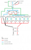
I am trying to create a dual source power supply that on one side can supply 0-150v DC low amps and on the other side 0-20v DC high amps. I have attached a VERY basic schematic that shows all the parts I am planning on using. Now here is my problem... both sources use the same output to load, therefore I am worried if one side is on and the other is off that the side that is on will back feed power into the side that is off and create a problem. If you wouldn't mind checking the attached drawing and letting me know if it is OK or if I need to add some more protection to stop the two sources from interfering or damaging each other. The only abnormal thing in the wiring is the transformers on the 0-20v DC side. Their DC ground output is on the transformer and NOT coming off the bridge rectifiers. This is the part that worries me. I believe that the bridge rectifier on the 150v side would stop any back-feed of current but since it can not be wired that way on the transformer side I am worried they will be damaged.

Thank you in advance for any help you electronic experts can offer!!!

Thanks,

Keith
 

Attachments

  • Dual Power Supply.png
    Dual Power Supply.png
    30 KB · Views: 174

davenn

Moderator
Trying to follow your cct is difficult its dreadfully complex for what should be relatively simple. why are there so many rectifiers? why are there so many transformer windings ?

It also appears that you are also rectifying the AC mains. This is not really a good idea,
in fact pretty flaming dangerous, as it gives you no isolation protection. If the rectifier goes short cct in any way you could end up with AC mains voltage going into the 150V DC cctry and into anyone touching that cctry.
you really just need a transformer that has 110V windings both primary and secondary sides with an additional ~ 20V secondary winding (with heavier turns = higher current)

I'm not a transformer expert, Militoy may chime in .... not sure if 110VAC will rectify and smooth to 150VDC you may need ~ 120V.

cheers
Dave
 

Attachments

  • Dual PSU.gif
    Dual PSU.gif
    2 KB · Views: 149
Last edited:
I'm not following the circuit either - it looks to me like you're rectifying the mains after running through the variac - but then also paralleling the rectified outputs of 3 series 14VCT transformers into the same output bus (also after having been run through the variac)(???). If you wire it up as shown in your schematic - expect maximum smoke.

As far as the output voltage - a FWB rectifier with a capacitor input filter will output DC roughly 1.25 x the RMS output voltage. That's assuming the capacitor is above critical capacitance - maybe 1000uF per amp load at 60Hz - and ignoring rectifier drop. So 150VDC is about right for 120V mains.
 
OK, I know my drawing is hard to follow, but I do not know how to draw a schematic so I did the best I could with a simple wiring diagram. Maybe it will be better to just tell you what I am trying to do and that might make the drawing a little easier to read.

I want to make a power supply that can provide 0-150v 25 amps DC and 0-20v 120amps DC. I would also like the + and - outputs or at least the - output to be on the same terminals so that I can use one shunt and amp meter on the power supply to read current, instead of installing two. I also want to be able to adjust voltage to anything I want hence the variac. A transformer that is rated for 120 amps DC is way to expensive, so I bought three transformers from car battery chargers that are each rated for 40 amps.

The reason there are so many bridge rectifiers is that is the only way to hook up these cheap transformers. Ideally there would just be two leads coming of the secondary coil but instead there are 5. One is DC ground, and the other 4 are end taps and center taps I believe. Each end and center tap have to be run through their own bridge rectifier for the transformer to operate properly. I was told these transformers are wired this way because it is cheaper.

Questions:

I have seen other people do this before, but is it dangerous to run the mains into the variac and then into a bridge rectifier for DC? I was told if the bridge rectifier shorts then you would have mains voltage coming out the terminals instead of DC.

Can I just put a 25 amp rated switch on the two ac outputs from the variac? This way each side of the power supply would be completely isolated from the other via the switch.

My problem with using an isolation transformer is two things, one I don't have room in the enclosure and two one that was rated for 25 amps ac is not going to be cheap. So if the switch is not going to work is there any other option?
 
OK – Now I see what you’re trying to do. There are a number of problems with the idea – but I don’t actually have a whole lot of latitude in my schedule today to sit down and go over each one all at once – so I’ll hit on the first big one – and I’m sure several others will jump in.

If your whole system was 100% efficient, and unity power factor – which it certainly won’t be – your high voltage section would draw 32.6A from the mains at full load. Most 115V circuits are limited to 15A – so you need to figure out where you’re going to get all that current. Now, let’s step into the real world –

A simple DC FWB rectifier with a capacitor input filter draws power with a terrible power factor – very high first quarter cycle peak current – and the current out of phase with the applied voltage. Still ignoring efficiency, you have to allow for RMS current that is 1.6-1.8 times your DC output current. This puts you up at something like a 50A service requirement – and then, add in more for power losses.

I would work on this aspect of the design first – consider what you absolutely, really need for the outputs – and then figure out where to get the mains power. I’d look at a 220V 50A main for a start. Then, you can look at the next output section, and start working out details. Oh - BTW - you'll also have to rate the variac accordingly. Maybe you can get away with lower output currents(???)
 

(*steve*)

¡sǝpodᴉʇuɐ ǝɥʇ ɹɐǝɥd
Moderator
problem #1 -- find a variac rated for 25A

problem #2 -- 20V 120A ?!?!

What do you need this for?

It almost sounds like you should be looking at a transformer from an arc welder, or a truly massive SMPS.
 
I already have a variac rated at 30 amps

I really don't need 120 amps 20v. Most of the time I am at 40 amps 12v, but I do some tests on single cell electrolysis that would be around 4v 80 amps.

Basically my exact same setup as pictured in my drawing, other than the high voltage dc side, is already in operation and performs flawlessly on a 20 amp mains circuit. But I will say that I have never taken it over 14v 80 amps.

The whole point of this thing in the beginning was thinking I could just add a BR to a second lead off the variac to do experiments with high voltage DC and low voltage DC considering I already had all the other parts in operation. But this does not seem to be a possibility, at least not without an 120 -120 isolation transformer. But the main thing I do not understand is why a DPDT switch controlling the two leads off the variac would not isolate the two circuits?
 
Also the transformers I have are from battery chargers, but they are basically the same thing as an arc welder transformer but a little better because they are rated at 100% duty cycle and not 50 or less like an arc welder.
 
Top