Hi,
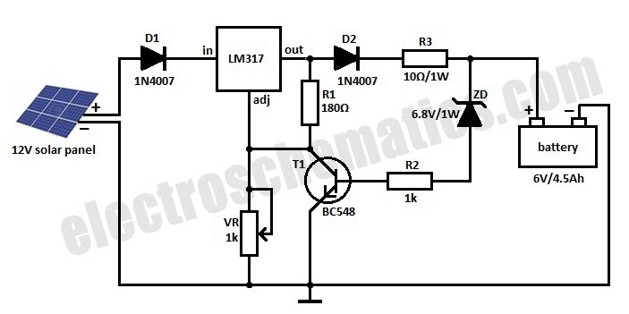
I found this simple 12v solar charging circuit online. http://www.circuitdiagram.org/solar-battery-charger-circuit.html. Can someone please help me understand it. I understand the output adjusting part of the LM317 ic. What I don't understand are the conditions how the transistor is turned on and off. Isn't DC voltage an open circuit to the capacitor hence the transistor will alway be off? What conditions would exist, which would warrant the .5ohm 5watt resistor to be required?

Thanks
I found this simple 12v solar charging circuit online. http://www.circuitdiagram.org/solar-battery-charger-circuit.html. Can someone please help me understand it. I understand the output adjusting part of the LM317 ic. What I don't understand are the conditions how the transistor is turned on and off. Isn't DC voltage an open circuit to the capacitor hence the transistor will alway be off? What conditions would exist, which would warrant the .5ohm 5watt resistor to be required?
Thanks