Maker Pro
Maker Pro

Help repairing car stereos: Delco 90's CD & tape player

Hi everyone, first post here.

I have a mid 90's Camaro, and I want to keep a working original radio/CD/tape player in the car. I have a couple of units, one with a cd, one with a cassette. I've had a ton of trouble finding any real information about these. No schematics, repair manuals, or really much "talk" online about fixing these. Seems that stuff from the 80's and before is somewhat better documented.

For the cassette, the radio/displays/buttons work, but the tape player doesn't play. I don't know who made these, but it's not the Blaupunkt units seen in the 80's Delcos. You insert a tape, and it doesn't run the tape forward at all. I don't think fast forward or reverse properly work, and usually the unit clicks constantly from a solenoid. Something to do with the auto reverse?

The CD unit has a problem where the display randomly flickers on and off. It's completely random, and sometimes is a quick flash, other times much longer. Also, the CD unit rarely plays. It whirs and tries to read, but usually comes up with an ERR message. These CD units were made by Technics, but I can't find any real information about them except some people mentioning replacing caps to fix them...with no other details.

I would really appreciate any help with this, or at least pointing me in the right direction to ask somewhere else about fixing these units. I can take more pictures if it helps.

PXL_20220428_204939394.jpg PXL_20220428_205809309.MP.jpg PXL_20220428_205818848.jpgPXL_20220429_230728975.jpg PXL_20220429_230750183.jpg PXL_20220428_210007335.jpg PXL_20220428_210017072.MP.jpg PXL_20220429_195144149.jpg PXL_20220429_195305427.jpg
 
Last edited:
The tape player issue will likely be one of lack of lubrication, loss of transport (rubber bands) and dirty electro-mechanical contacts. SInce many of the motions are instigated by a mechanical movement (insertion of cassette) you will have to identify the parts that move and any contacts that close, lubricating and cleaning as you go. Your photos don't really help.

Have a look for opto-couplers too (slotted opto sensors) - check for dirt between LED and sensor.

The CD display will likely be the connections between display and board - this may be a 'zebra strip' (conductive rubber strip) that just needs cleaning and the pressure between display and circuit board confirmed to be present and correct. The worst case scenario is a laser diode failure for the error message but quite often the use of a CD lens cleaner disk will sort out the issue.
 
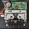
I've added a couple of photos of the tape mechanism inner to the original post. Down below I have a photo of where the tape goes inside the mech.

The main drive belt was fairly deformed and not really soft anymore, so I substituted a similar size belt I had. I'm not really sure about whether the routing for that is correct, or if any other belts are missing since I have nothing to compare it to.

I've tried lubricating the metal to metal sliding/moving assemblies with some light compatible oil. Nothing excessive. The small blue solenoid in the above picture is the one that constantly clicks. The rubber wheels seem fairly soft in the back, and I cleaned the sensor + blew air through the mechanism.

PXL_20220429_231352791.MP.jpg
 
There are two capstans - shiny metal poles - that holds the audio tape between and the pinch roller and only one of these should be 'closed' together at any one time depending on the tape direction.

Spin the motor by hand and, with a tape inserted, ensure only ONE capstan/roller is engaged. The solenoid sounds (to me) to be like the auto-reverse mechanism which engages when it detects a 'taught' tape (i.e. end of tape) and is cycling because the tape isn't 'free'. This could be as a result of an incorrectly fitted drive belt (driving the two reels simultaneously and in opposite directions) but I can't determine this without seeing the mechanism working.
 
Thank you for the responses.

I'll have to try some things with the tape player. For the CD, I can check the ribbon cables and try cleaning the cd lens, but afaik these Technics units are known to have nonplaying issues over time that are a more detailed problem.
 
Technics units are known to have nonplaying issues over time that are a more detailed problem.
True - laser module failure. A few years ago getting spare laser assemblies was quite easy. Here in the UK a company called CPC had a rather extensive range but they've gone right out of fashion now leaving you the second-hand market as the only route to a potential fix.
 
No joy so far on the CD unit. I pulled the display related board out and didn't see any obvious cracked solder joints. I reseated the ribbon cables and main connector, and tested the traces & connector wire continuity with a meter and everything checked out. Still getting display issues.

I also carefully cleaned the laser lens of the CD unit, and no change on that issue either.
 

Harald Kapp

Moderator
Moderator
It whirs and tries to read, but usually comes up with an ERR message.
This can also be caused by a dirty pickup disc. The CD then is not brought up to speed but sips on the pickup. Cleaning the pickup with alcohol may help.
 
I reseated the ribbon cables and main connector,
This issue is probably 'deeper' than the panel and ribbon cable and inside the LCD module itself where, commonly, connections to the LCD are via a soft rubberised strip (called a zebra strip).

Post a pic of the LCD part (top and bottom) so we can confirm.
 
Ahhh, that's called a VFD (Vacuum Fluorescent Display) and is solidly mounted and driven by the dedicated multi-pin chip under it. The only potential issue I can see is corrosion (or deposits) on the solder side where the white connector is. Clean that up using IPA (solvent) and potentially resolder the joints.

If that doesn't fix it then test the continuity of each wire between the two boards. The only other way the display is 'wonky' is from communication errors which is a whole 'nuther' level of testing......

The little blue device beside the lower connector on the main board is the timing component for the microcontroller that 'may' have drifted in value - see if you can read the number on the side of it. They are readily available. If the timing changes outside a certain level then the reciving device (the dedicated chip under the display) can't decode the data stream.
 
I have checked the continuity of the brown, white & red wires between the three connectors to the other board & aux plug and they tested fine.

I kind of feel like the "deposits" around the solder joints in the picture are some kind of potting or coating just lifting and flaking off over time, but maybe it's more than that.
 
I have checked the continuity of the brown, white & red wires between the three connectors to the other board & aux plug and they tested fine.
The little blue device beside the lower connector on the main board is the timing component for the microcontroller that 'may' have drifted in value - see if you can read the number on the side of it. They are readily available. If the timing changes outside a certain level then the reciving device (the dedicated chip under the display) can't decode the data stream.
 
I have tried working on the display issue. I reflowed the pins for the display board, and all the connector pins between. At first, it seemed like it worked for a couple of days, but today the display started to modulate in brightness and flashed off and on once.

I'll look at the component you mentioned.

I was talking about the pickup that sits on the motor spindle and turns the CD. Not about the lens.
I can look at this, but it will take doing some more serious disassembly of the mechanism first. Everything I've read in other places point to the surface mount caps being the issue with the mechanism.
 
Last edited:
The little blue device beside the lower connector on the main board is the timing component for the microcontroller that 'may' have drifted in value - see if you can read the number on the side of it. They are readily available. If the timing changes outside a certain level then the reciving device (the dedicated chip under the display) can't decode the data stream.

What is that exactly? A varistor, or a cap? Printed on it is:
CSA
120 MT
 
Yep, it's a ceramic resonator only a 2-pin variety, not the 3-pin I linked to above. They are readily available BUT they are also pretty reliable too so I'd be surprised if it's a dud or off frequency. The only way you can tell, without recourse to a frequency meter or oscilloscope, is to replace it though. Being as cheap as they are it's a lot easier than sourcing a 'scope!
 
Top