Maker Pro
Maker Pro

help in fixing national panasonic stereo model RX - F80 - 2

pharaon . . . . . . .


Looks like the long path of that BLUE line confirms that switch being associated with the Tape portion .
Typically when the player is in Tape position and being in a turned on state, the electronics is working but just waiting for the play pushbutton to be pressed to activate the motor.
That blue trace is going to the multiposition switch associated with the tape play position.

That leaves the DEF contacts of the switch to likely be for the radio power of the unit.

It looks like you have pulled up the RED battery wire from its soldered in position, but left some wire bits sticking out to the side. None of them are shorting out to the foils just beside them . . .are they ?

Put on headphones , good batteries in the holder, slide the Radio -Tape switch toRadio, be sure no tape player buttons are pushe in and latched, take the RED battery wire and connect to a 100 ohm resistor and touch its OTHER end temporarily to our switch, center terminal E.
Is there any noise from the phones? , if so, reconnect the resistor and try to tune in your strongest AM radio station.
If that doesn't work . . . .try the procedure with a 47 ohm resistor.
If that doesn't work . . . .try the procedure with paralleled 47 and 100 ohm resistors.

I was certainly hoping to find my old Sony Walkman of 46 years ago that also worked with 2 cells, but can't locate it.
I waswqnting to make comparison with it to see just how LOW of a voltage supply can be used and still be having the AM radio portion just barely working.
I am thinking of the FM portion as being more voltage critical, thus, my suggesting the simpler AM portion

Hope this makes music for you .

73's de Edd
 
Last edited by a moderator:
Sir pharaon . . . . . . .

The reason for the slow, yet methodical, procedure for seeking out the correct connection of the power lead to the Radio portion , was to POSITIVELY, avoid any chance of damage to the
unit by applying FULL 3 volt power to the WRONG place.

The use of the 3 values of series resistors, was incrementally limiting the potential power level being applied.

Once you found that the progressive lowering of resistance, finally found that magical minimal power operational level to be with that 47 ohm resistor, we might now confirm that line as being the point where
the + RED battery wire gets connected.

HOWEVER, if being myself doing this , I would do a tracing out of ALL of the copper foil path that is being connected to that E terminal of the switch, at some solder blob on it, I would expect to find the original
short pieces of the RED wire when it broke off in the solder.
If you can't find that original connection, just make your new RED battery wire connection anywhere along that foil path that goes to switch terminal E.
You can see on the BLACK negative battery wire and how they made its butt connection to the foil path.


iUQJLB2.jpg


ASIDE . . . . .

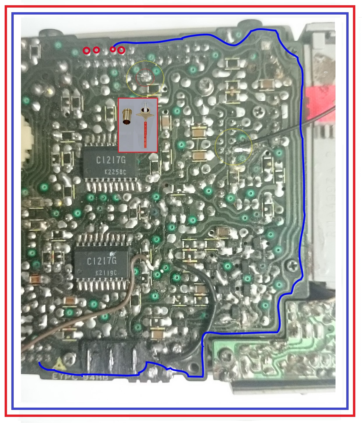
In looking at the place where your old RED battery wire connection was made ***, it certainly looks like a valid point for that connection to be.
The situation being the star split hollow rivet being used at that point.
Look very closely at the solder formation around that point, and then at the inset illustration of a common hollow rivet and a hollow star rivet.
When one of the latter is crimped into place the star points of the rivet move outwardly to make a larger solder contact area.
The RED tinned lead wire then passes thru the rivet and is soldered .
That procedure is commonly used for single wires that come to a PCB and need to be securely terminated to the board with plenty of solder connectivity.
They are mechanically and electrically superior, but have a fault of failure to repeated lateral wire flexes.

***
If you trace the foil path from the inital old RED battery wire connection, it passes up and then to the left past the central area of the Radio-Tape switch and
up to a greener dot on the board where a connection is being made thru to a foil on the other side of the board.
To see if this green dot interconnection might possibly have failed, use an ohmmeter to probe into the foil just to the side of this board sides feed thru dot
and use the other probe into the foil just to the side of the dot on the other side of the board, confirm a short if that interconnect is being good.


73's de Edd
 
Last edited by a moderator:
.

Sir pharaon . . . . . . .

"thanks alot" . . . . . ..which I hope is meaning . . . . .IT WORKS ! ! ! !

Any chance that the tape player is also working now ?

If being my job . . . . for my final test . . . .I would have series inserted DC current metering . . .initially placed in its amps range . . . . . into the battery supply line and have no buttons pushed on the TAPE player
and the slide switch in the RADIO position .
Have the volume at minimum and switch current metering on down to milliamperes range to see radio current consumption and then flip the TAPE-RADIO switch to TAPE to disable the RADIO and then see
that there is then no current being pulled from the battery .
The tape circuitry would be disconnected also, since it depends upon its push button cluster to get power.

Thasssit . . . . .

73's de Edd

.


..
 
Last edited:
I will look thru my inherited, brother in laws, amassed techno files and paper trail info next week .
In the interim, tell us ALL that you can, as to where the basic problem with the unit seems to be, or if it is just being a TOTALLY dead and inoperative unit ?
 
Top