Maker Pro
Maker Pro

Help fixing old walkie talkie

Hi!

Hope someone here can help me out on fixing this old two way radio I have. It is a Midland 13-723.
One of the variable filter coils needs replacing. On the metal housing it says 450 something blue colour. The rest is smeared out. There are other similar coils on the pcb with different colours(yellow, black, white, pink). Most of them I am able to read what is written on the housing and they say
2E
480(1 or l or I)
3DCT
They are from Mitsumi.

I have tried to find schematics but couldnt. I have contacted Midland, but they just say that this is a unit that they no longer sell and cant support.
I cant find any blue mitsumi coils and I am not sure if the colour even matters.

Does the 480(1 or l or I) mean frequency?
 

(*steve*)

¡sǝpodᴉʇuɐ ǝɥʇ ɹɐǝɥd
Moderator
perhaps a photo and a description of what is wrong with the part and the symptoms of the fault would help.
 
.


Sir ATA . . . . . . .

You got answers . . . I got some GOOD questions . . . . . in order to fine tune my design analysis.


Is / was there ever a CB band in Denmark ?
What is the significance of this unit ?
Is it nostalgic to you, or once a possession of a passed on relative ?
Or possibly, you are being a collector of old electronics . . .as this one dates to being back from the seventies.
Are you familiar enough with electronics and repair to be able to handle the job / repair ?
Do you have a companion unit . . as they are used in pairs.
OR . . .in reality . . . . are you equipped with a receiver that can receive the CB / AM radio spectrum up around 26-27 Mhz ?

I just took an initial cursory look and gave you an analysis of the photo which you supplied, along with the
Edd-u-cation, being supplied just below.

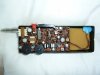
My immediate thought was that the "absentee" was being a dirt common 455 IF transformer from that era.
Then I see that ALL three are being present . . .see my markup . . . by their layout path on the PCB and their VERY COMMON casing / slug color coding.
The top right corner of the board is looking to be the converter area of the receiver.
That would be where 27 Mhz incoming signal is converted down to a replicating signal, but being at 455 Khz . . . . or possibly they double converted down to an intermediate 1750Khz and then converted on down to 455.

This is just a 3 channel crystal controlled unit .
There are capabilities of 3 transmit crystals to the left and 3 receiver crystals to the right for the 6 sockets.
If you pass me the frequencies marked on all of the crystals, I might THEN be able to then confirm the receiver portions single/ versus/ double conversion design quandry.

The marked up PINK audio-modulator and squelch area should not be of interest to us now.

TESTING:

Getting back to the consideration that our problem is having the receiver portion now inoperative, but not having been told yet if you have methodology of tuning in all CB frequencies.
Taking that as a possibility .
I'm going to ask you to battery up the unit and monitor on the CB band, and I fully think that there is great odds that the transmitter will work and that you can pick up your voiced signal.

That confirms only the receiver section being our problem.

RESOURCES:

If I find good answers above along with your capabilities, I will make a short trek out to my "Radio" ranch . . . go out to the " mule barn" where my surplus /older technical archives are stored and dig-dig-dig deep to find Sams CB Photofact manual # 56 and scan the exact Schematic for that Midland unit.

Only then . . . can I be able to analyze down to the very minute picofarad or sub microhenry . . . to fully see what that involved corner circuitry is being.

Thassssit . . . . . .

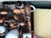
BTW . . . . the suggested radio museum is a dead end . . . no schematic there . . . . . but I DID lift the fulfilling inset photo from there.


UNIT REFERENCE :

Stand back . .waaay back . . . . .as it gets . . . . . bigger . . . . . MUCH BIGGER !

uk1Cwqc.png


73's de Edd


.
 
Last edited:
.Is / was there ever a CB band in Denmark ?.

Back in the 80's where I got this unit and later a nordland 01 1400 base station, the where still alot using these walkies. Today most of the channels are dead silent. But in some alotment gardens(thats what google translate gives me) CBs are being used and according to what I have read, should be getting more and more popular.

.What is the significance of this unit ?.
Is it nostalgic to you, or once a possession of a passed on relative ?


I got it about 30 years ago from someone. It has memories attached to it. If not, I would probably have binned it.

.Are you familiar enough with electronics and repair to be able to handle the job / repair ?.

Hard to say. Depends on what I have to do. But I'm willing to try.


.Do you have a companion unit . . as they are used in pairs..

I have a nordland 01 1400. If I can get it going. The transformer is out. But I can use a battery. I also have an Onkyo TCR-111A but unfortunatly with 27.125mhz and the Midland has 26.550 and 26.975.


By pressing the red call button on the Midland the beep can clearly be heard on the Onkyo although different frequence. And on the Nordland it can be heard on channel 2. But no sound at all the other way round.
 
Last edited by a moderator:
One more thing. I n have discovered that transistor C1018 next to the pink coil is getting really hot.
 
.


Sir ATA . . . . . . .

Great info !
Now you have convinced me of my need to go dig out that manual and then lets continue the units analysis and troubleshooting.

By pressing the red call button on the Midland the beep can clearly be heard on the Onkyo although different frequence.
And on the Nordland it can be heard on channel 2.


OK . . . . .what is happening is that the VERY CLOSE proximity of the two units is making the transmitted STRENGTH of the Midland, "swamp" the receiver input section of the other Nordic unit.
With that STRONG signal able to be received on many nearby channels.
That would not be the situation, if the units were separated some MUCH GREATER distance, but it is, when the units are side being by side.


But no sound at all the other way round.
Logical, since our "missing" part is being a critical part of the Midlands receive section.


One more thing. I n have discovered that transistor C1018 next to the pink coil is getting really hot.

My resolution of the "blowup" of the photo is not definitively letting me pick out the "pink" coil
/ or / coil shield / or / even adjustment slug.
BUT I think that I certainly am seeing TWO of those 2SC1018 transistors being utilized in your unit .
In the RED LINED transmit section, there are two axial coils . . .probably serving as RF chokes and 3 RF coils that are arranged in a triad.
With my educated guess, that the top left unit might show a splash of PINK on it.

The power output 2SC1018 is at the top and between that RF output tank coil to the top left corner and the other right top corner coil is the tuned circuit feeding that transistors base.

At the area just above the crystal bank, we are seeing the other 2SC1018 used as the driver of that just mentioned RF power output 2SC1018.

It seems like, in consideration of limiting the sticking up of the heat sink tab, that they reformed and coiled the tab up into a circle to limit its vertical extension profile.
This case uses a TO-202 profile with the somewhat thin heat sink tab coming out of the side of the plastic case.
One might compare it to a TO-220 case . . . . but you would never form one of those THICKER TO-220 tabs, in the manner such as these have been.

As for the heating of the final transistor , I HEAVILY suspect that is probably due to 40 + year old electrolytics and, in this specific case, PARTICULARLY the last one that is on the DC supply line that feeds the RF final transistor .
It is not properly bypassing and the RF final transistor is being over stressed due to that condition..

NOW . . . .

(Appropriately set to Elmer Fudd type music) . . . . . .A hunting we will go . . . . . a hunting we will go . . . . . . . . for my digging out of that Midland manual.

73's de Edd


.
 
Found out that nothing gets hot if just the walkie is just turned on. But when pressing and holding the transmitter button, it heats up very transistor heats op very quickly.

P1030689.JPG

As for the transmitting, Only the call signal came through. No voice. Seems the speaker isnt picking up any sound at all.
I walked down to the basement(live on the second floor) and the signal still came through clearly. Ok not much of a distance but still.
 
Sir ATA . . . . . . .

Got the book, after dig-dig-digging but can't digitalize its info until a day or so after our Amerikanski Memorial day.


73's de Edd
 
Last edited by a moderator:
Sir ATA . . . . . . .

Behold all of your relevant repair data for that unit , plus I added the E-cap page, in consideration of all of the the old ones in that unit.
As making that the very final feat.


dwQplxg.jpg


If being my unit to repair, I would be using this transformer . . . as Midland specifies L3 to be peaked at 27.085 . . basically midband. . . and this unit can swing from 25-30 mhz.

http://www.ebay.ie/itm/TOKO-MKXCS-K...553151?hash=item2a6951297f:g:DN8AAOxyrx5TlfQb

Otherwise, you would be having to find yourself a 10.7 Mhz 3rd IF transformer and be taking off about 2/3 of its turns to resonate on up to 27 Mhz.

73's de Edd
 
Last edited by a moderator:
This is great. I'll order one. Probable a bit too big to fit properly but perhaps no problem.
In the partslist of coils it just says rec. rf at L3. From where did you gather the data?
When looking up the 3e4500b on google I find nothing.
 
Top