Maker Pro
Maker Pro

HELP - DIY AC conversion to steady flow DC

Hi ALL!! I'm new here.

I'm trying to create a conversion for my Lincoln AC-225 arc welder, to add DC welding capability (as opposed to paying an extra $400 for a production unit).

Here's what I have so far, with the addition of a properly sized bridge rectifier, I can successfully convert the AC waveform to DC. But, the waveform is not steady like I need it to be (as seen on the right of the following image)...

9693-500px-Gratz.rectifier.en.png


For DC welding, the DC current needs to be as smooth as possible, otherwise the welder has to deal with constant arc instability (thus, a crappy weld no matter how great at welding the guy making the weld is).

I have read a lot about adding a capacitor to the output to "smooth" the current to a "ripple" (shown in the next image), but due to the voltage and amperage involved, an inductor might be a better choice. Please post your opinion if you disagree.
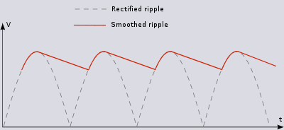
9694-400px-Smoothed_ripple.svg.png


So here's my dilemma, I can't seem to be able to find any info (that I can understand) that would help me size the inductor coil to this application.

Here's the current specs:
48-53V @ 30-225A

The voltage is almost a constant.

The amperage is selectable on the AC side of the rectifier via a knob on the front of the welder. Available max amperage can be selected from 30A to 225A. While welding at whatever amperage is selected, the actual amperage can vary depending on many factors, but not to exceed the max amperage selected via the amperage selection knob.

So that's about it.
I could use your help to finish this project.
 
Well from my understanding an inductor resist changes in current by releasing it's stored energy back into the system in the form of voltage to try and keep current flowing. From what I read the other day from resquline, inductors only work at high frequency. So I don't think that is what you need.

Probably just a decent sized capacitor bank will do, wire them in parallel and the capacitance will simply add up.
 
Heya, welcome to the board!

Wow, 12kW of load? That may be tough.

Indeed. An inductor to 'smooth' that 120Hz would be... large, to say the least. Particularly at those currents, to keep the core from saturating or even melting the coil, it would be prohibitively big. Not an option, as far as I'd be concerned.

I take it there is a transformer before the bridge to take it from 120/240 to ~50Vac? I calculated something along the lines of 2F.. (yes, 2 Farads) to even get a 5% (~3V) ripple. I don't know enough about arc welders to say what kind of ripple current the caps would see, but I'd expect it to be hefty.

I suppose it could be done, but it would be expensive. Few hundred dollars in caps, as a guess... you'd probably pay more than you would if you bought a production unit, unless you can buy in 10k+ quantity anyway. :) Some type of high power SMPS would probably be better, but now you're talking about a design way over most of our heads here.

Edit: Oh yeah, and you'd be getting ~75V out of the bridge, not the ~50V the welder would need, btw. I'm assuming the commercial units are using some type of 12kW+ power supply, since as you said, you'd need to precisely regulate the output current anyway.
 
Last edited:

(*steve*)

¡sǝpodᴉʇuɐ ǝɥʇ ɹɐǝɥd
Moderator
A better solution is to bridge rectify 3 phase AC. As your unit appears to be only single phase, that's not a very helpful piece of information :)
 
I don't know how much the ripple needs to be suppressed to do the job. That value will greatly affect the size & cost of the add-on's.
Old tube equipment sometimes used inductors in addition to capacitors in their HV power supply. These inductors were almost as big as the power transformers.
Large capacitors may lead to large bangs & sparks flying upon ignition of the arc. An inductor (though big) would be preferable, and would retain the nominal voltage output.
If you could rectify 3-phase instead this would certainly be the most preferable method.
 
Heya, welcome to the board!

Wow, 12kW of load? That may be tough.

Indeed. An inductor to 'smooth' that 120Hz would be... large, to say the least. Particularly at those currents, to keep the core from saturating or even melting the coil, it would be prohibitively big. Not an option, as far as I'd be concerned.

I forgot to add, there is a 20% duty cycle on this welder, so there is ample time between welds for cooling of the equipment (that I'm already bound to).

Large is not a problem for this project.
If need be, I'll create this modification as a separate unit (not physically attached to the existing welder). That allows me the freedom to add wheels and a handle to it's custom case. So large is not an issue.


I take it there is a transformer before the bridge to take it from 120/240 to ~50Vac?

Yes, it takes 220V @ 50A and converts it to selectable amperages between 40-225A through "taps" in the transformer (somehow, that's a bit beyond my understanding).

I read on another forum that this conversion works out to 53V output w/ a little loss, so they are assuming around 48V out @ the selected amperage.

Their math might be off, I'm still trying to figure out how to check it.


I calculated something along the lines of 2F.. (yes, 2 Farads) to even get a 5% (~3V) ripple. I don't know enough about arc welders to say what kind of ripple current the caps would see, but I'd expect it to be hefty.

I assumed it would be something really large like that. Thanks for taking the time to do the math :)


Large capacitors may lead to large bangs & sparks flying upon ignition of the arc.

Yes, which would blow the electrode to bits, scare the hell out of my wife, make the cat run away (never to return), and surely scare all the wildlife from ever visiting our yard again.


...Some type of high power SMPS would probably be better, but now you're talking about a design way over most of our heads here.

Yup, I looked into that on wikipedia and a SMPS is a bit too complicated for this project.


Edit: Oh yeah, and you'd be getting ~75V out of the bridge, not the ~50V the welder would need, btw. I'm assuming the commercial units are using some type of 12kW+ power supply, since as you said, you'd need to precisely regulate the output current anyway.

Not sure. I need to look into that better.


A better solution is to bridge rectify 3 phase AC. As your unit appears to be only single phase, that's not a very helpful piece of information :)

Yea, if I had 3 phase coming into the house, and a 3 phase welder, I could simply toss the bridge rectifier on to it and be done with it, since the rectified 3 phase wave is already steady enough for my needs.

Unfortunately, single phase is all I have to work with.
 
So let me ask you guys this, is there a range that the inductor should fall within (in regard to size), or do I just have to make sure that it's not too small?

Meaning, is it theoretically possible that I could use an oversized inductor (within reason) without negative effect?

What effects might happen if I oversize it?
 
Huh, I was looking around at various inductors... not as big as I had postulated. A 200A, 300uH is ~7.5" x 7.5"... the inductance seems a bit small, I would guess you'd need many mH at least, but even that one I found was going for $350.

Of course you'd need something rated 250A+, and probably more to be on the safe side... but I have no idea what kind of inductance would be necessary. I can't even find any formulae for such an application.

What values (or parts) would you recommend, Resq? Or what combination of caps/coils would work best?

As for oversizing, there is no problem oversizing... I just doubt you'd be able to. But hell, I don't know. :)
 
I won't be buying an inductor, so cost is not an issue.
I will be building it myself.

On a side note, I was thinking that if I used a thick iron rod/tube that had a hole through the center, I could rig up a few aluminum or copper heatsinks inside it and blow air through it to remove core heat. This might aid in preventing the core heat from toasting the coils.
 
Inductors can be viewed & calculated like capacitors, just swap volts & amps in the formulae. L[H]=E[V]*(delta I[A]/delta t)
A cap of 1F being charged with 1A will increase its voltage with 1V/second, and an inductor of 1H having 1V applied to it will increase its current with 1A/second.
One can always solve the math graphically; draw a rectified sine wave on a scaled paper [A & s], then draw a sloped line between the sines around 71% of the amplitude.
That sawtooth line is the current that'll pass. It won't "charge" to the top of the sine like a cap will, instead it'll swing around 71% (= set output curent) of the peak level.
The slope (being as large as you "dare" it to be) translates into inductance. The steeper the less inductance needed. Then multiply the slope inductance with 50[Volts].

Manufacturing the coil is a whole lot harder. The iron shape, mass, & type affects the result a lot, and you have to take care that it doesn't saturate too much (use air gap).
Too small and saturation cuts inductance down to almost nothing. More iron = less copper. (The copper could even imagined to be in the form of a water cooled tube.)
The only thing you can "skimp" on (due to the duty cycle issue) is the copper wire. Also use thin sheets of iron instead of massive rods to cut the eddy current losses.
I'm sorry I can't help you much with estimating the actual dimensions of the inductor.
 
Well, best I could come up with is a pi setup:
one 2.2mH inductor
two 22,000uF caps.

That would keep the 50V 225A output, with ~2V ripple.
Without the caps, you're looking at ~8V ripple, 43V, ~190A.

I still think the inductor is going to be a couple feet by a couple feet and weigh a couple hundred pounds.

Edit: I guess the best thing to do is experiment... see what the weld quality is with varying ripple. Maybe 5% ripple is way overkill, and 10, 20% would work ok. I don't know anything about welders. :) Go with the largest inductance you can get, while ensuring the current carrying capability of the copper is high enough. More importantly, ensure your core does not saturate. Actually measuring this would require an o-scope at a minimum, and you'll probably end up with an f-all strong electromagnet, so keep other ferrous items away. Btw, I'm not worried about the copper conductors here, that's easy and relatively small... it's the core. Just like the caps would need to be 2F if going with cap only filtering, for inductor only filtering the magnetic field storage needs to be huge. That storage ability comes from the core, which will need to be massive at those currents. That's why I suggested the pi filter option, to cut down on all values. 12kW is just a ****load of energy. Another problem with using no caps is that in the lower current settings, the output ripple goes up, a lot. You'd need something like 100mH if just using an inductor, to cover your range.

Also be aware that the current will not be instantaneous with an inductor smoothing your ripple out, but will ramp up 'slowly'... I don't know if that will affect your welding capability. The larger the inductance, the slower the ramp. Also, the statement I made earlier about oversizing not mattering: it does matter, now that I've simulated it. Sorry, I should've known, but the higher the inductance the lower the voltage out. If you end up going with just an inductor and no caps, you'd need to change the inductance value to maintain your 50V output. With this pi setup, at lower current draws you're going to end up with some ringing, too. It may take the voltage output up to 100V or so for a split second. I don't know if that would destroy your welder. (But the bright side is that there is virtually no ripple at the lower current settings.) Cap only filtering would take care of both problems, but as Resq said, there are other issues.

See attached quick simulation for the pi filter. (R1 is just there to simulate your 225A draw at 50V.)
 

Attachments

  • Sim_Schematic.jpg
    Sim_Schematic.jpg
    134.1 KB · Views: 135
  • Sim_Waveforms.jpg
    Sim_Waveforms.jpg
    121.3 KB · Views: 139
Last edited:
I really appreciate the work you've done on this.
What software are you using? I can't quite make out the name of it there in the pic.


I still think the inductor is going to be a couple feet by a couple feet and weigh a couple hundred pounds.

Edit: I guess the best thing to do is experiment... see what the weld quality is with varying ripple. Maybe 5% ripple is way overkill, and 10, 20% would work ok. I don't know anything about welders. Go with the largest inductance you can get, while ensuring the current carrying capability of the copper is high enough. More importantly, ensure your core does not saturate.

A ripple of as much as 10-15A would be better than doing nothing and having a wave dropping to zero 60 times a second. Hell, I would even be willing to settle on as much as a 50% ripple if that's what It takes to realistically smooth the waveform vs. size, weight, and other design constraints.

Also, the normal average welding current is between 100-150A, and I can't remember the last time I used a current above 160A or below 70A. So I think the system should be maximized for this average range.


... the current will not be instantaneous with an inductor smoothing your ripple out, but will ramp up 'slowly'... I don't know if that will affect your welding capability. The larger the inductance, the slower the ramp.

If anything, the welder could use a bit of boost when striking the arc. Having to deal with drops in volts/amps on startup is a big issue. Getting the arc to initially start is hard enough with even the best of stable currents. Too low of a voltage/amperage and the electrode sticks to the metal you're trying to weld (thus making the welder frantically do whatever it takes to disconnect it and start over).
 
Last edited:
That's Altium Designer. Very nifty schematic capture / PCB layout / SPICE program.

Would you happen to have that "project" pictured above, saved?
If so, could I have a copy?
file name: Input_Filter.PrjPcb

I'm trying to recreate what you did there in Altium Designer, but I'm having trouble getting Altium to show the AC volts waveform AND the AC Amperage in the same simulation.
 
I didn't keep it, unfortunately. Should be asy to replicate though. You mean the AC input? Try putting Vin and V1#branch options under "Active Signals" in the analyses setup screen.

Vin is the voltage coming from the AC source, branch is the current.

Btw, to set up the 50Vac, you should set the ac source to 70.7 volts... when you set the magnitude of the source, they're asking for a peak value, not the RMS. 70.7 pk = 50 RMS.
 
Top