Maker Pro
Maker Pro

Half bridge inverter

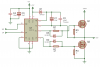
I was build an inverter project with ir2110 driver and two mosfet IRFP460 which have 500 Volt on Vds and max current 20A...
It works well on resitif load like light bulb ... but when i change the load in to inductive load (1 phase motor induction) that have max current 4.5 A the mosfet blown ...
What should i do ?
Im not forget to ad a flyback diode paralel to Mosfet ... so i guess the reverse voltage from inductive load wont cause problem .. please Help ...
 

Attachments

  • IR2110 - 2.png
    IR2110 - 2.png
    44.9 KB · Views: 142

CDRIVE

Hauling 10' pipe on a Trek Shift3
Your MOSFET output circuit doesn't look correct to me. Please post the link to where you found your schematic.

Chris
 
when i change the load in to inductive load (1 phase motor induction) that have max current 4.5 A the mosfet blown ...
How/where are you connecting the motor? A 1 phase induction motor needs alternating current. Your 1/2 bridge circuit provides only chopped DC ! DC can fry an induction motor.
 
Sorry guys i forgot to tell you that i didnt connect the source of the low side mosfet in to ground ... but i connect it to the negative voltage (-310V)
So the output is alternating current isnt it ?
*see the red circle
 

Attachments

  • IR2110 - 2_1.jpg
    IR2110 - 2_1.jpg
    72.1 KB · Views: 116
I use sine PWM method ... triangle frequency is 3000Hz... and the sine is 50Hz ..
And the dead time is 24us ... but the mosfet is ringing a little...
I also add a fuse on drain of the high side mosfet and source of the lowside mosfet ..but the mosfet still blown without melting the fuse first if the load is inductive load ...
 
Last edited by a moderator:
C1 . . . .
" For low frequencies such as 50Hz, I use between 47µF and 68µF capacitance. For high frequencies like 30kHz to 50kHz, I use between 4.7µF and 22µF. "
Being considered ?
 
C1 . . . .
" For low frequencies such as 50Hz, I use between 47µF and 68µF capacitance. For high frequencies like 30kHz to 50kHz, I use between 4.7µF and 22µF. "
Being considered ?

Yes the sine wave is 50HZ ... but the output is square wave and the switching frequency is 3Khz ...
22uf is work i guess..
 
Where? I don't see them.

Chris

Here is my mosfet inverter circuit ...
I add a diode ... flyback diode just like in the picture ...
But i only make a single phase inverter half bridge ...
I use UF4007 for the flyback diode ...
 

Attachments

  • DRIVER.jpg
    DRIVER.jpg
    35.3 KB · Views: 121
The Mosfet blown without getting hot ...
Is it because of short circuit ? Or is it because the noise from induction motor?
Or dead time is not enough ?
Well i'll try increasing the deadtime for now
 
The diodes as shown do not restrict the drain voltage which can be very high due to the inductive load.
Snubbers are often used to restrict the peak voltage. This is not my area of expertise.
 

CDRIVE

Hauling 10' pipe on a Trek Shift3
Here is my mosfet inverter circuit ...
I add a diode ... flyback diode just like in the picture ...
But i only make a single phase inverter half bridge ...
I use UF4007 for the flyback diode ...
27606-cee610fe4780f5b463b83b390d6c1ca5.jpg

I suspect it's just a language gap but that driver looks like it's intended to be a 3PH driver. Are you saying the protection diodes are configured like that but that's not exactly your circuit? If so it would help to provide us with schematics that represent your circuits 'EXACTLY',.... not 'like' or 'similar' to them. Doing so will help in reducing confusion. Especially for those of us that are totally unfamiliar with the IR2110. ...Like me. :)

Like Duke, this isn't my area of expertise either, so it may be just me that's getting confused. ;)

Chris
 
Last edited:
Top