Maker Pro
Maker Pro

Ground loop of Agilent 33250A

Hi all,

I have some questions about the manual of Agilent 33250A,
"
Ground Loops

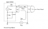
Except for its remote interface connectors and trigger connector,
the 33250A is isolated from chassis (earth) ground. This isolation helps
to eliminate ground loops in your system and also allows you to reference
the output signal to voltages other than ground. The illustration on the
following page shows the function generator connected to a load through
a coaxial cable. Any difference in ground potentials (VGND) will tend to
make current IGND flow in the shield of the cable, thus causing a voltage
drop due to the shield’s impedance (ZShield). The resulting voltage drop
(IGND x ZShield) appears as an error in the load voltage. However, since
the instrument is isolated, there is a high series impedance (typically
1 MΩ in parallel 45 nF) in the path to oppose the flow of IGND and
thereby minimize this effect.
upload_2014-12-16_12-18-56.png"
My questions are:
1. How does the Vgnd being produced? If there is a Ignd, then it means chassis ground and earth ground are connected to each other(which is used as the common method to prevent shock hazard), then shouldn't the potential difference be zero?
2. May I say that even if there is no Ignd, the VL is still not equal to Vout due to the exist of Zshield?
3. Is the source signal on earth a floating one or grounded one?
 
Last edited:
Hello. Answers to your questions which is my opinion only.

1) Current in the ground wire will cause Vgnd. Ground potential is not zero, only in theory.
2) No, when no there is no current in the shield (Ignd) you can't have a voltage drop across the shield so this can't effect the Vout.
3) I don't understand your question. Earth is ground in my book. Whether it's connected to chassis for safety or not. floating means isolated from something like the earth of a system. If there is an electrical connection from ground to the common of the circuit then this is not technically floating. But they have a 1 Meg resistor between ground and the signal source effectively isolating them.

Adam
Thank you for your reply.

For answer 1, may I say the current is determined by Vgnd/Rwire? If it could be, then how could the 1Mohm resistor and the capacitor reduce the effect of Ignd? or more clearly, reduce Ignd?
For answer 2, no ground current doesn't mean no current. upload_2014-12-17_8-49-41.png
the Zshield still acts as voltage divider, reduce the voltage which should be apply on the load.
For answer 3, just as you said, on the one hand, the earth is directly connected to chassis ground which is the common of the circuit, so it should be considered as grounded. On the other hand, there is the 1Mohm resistor, isolate the earth from the source, so it seems to be floating. There is a contradictory point here which make me confused.

Again, thanks for your reply and hope we can discuss more.
 

Attachments

  • upload_2014-12-17_8-49-16.png
    upload_2014-12-17_8-49-16.png
    84 KB · Views: 148
The current loop for what would be Ignd has now has a very high impedance in it. So not much current can be in the loop. This reduces the current in the shield to basically just the signal return current so has little effect on the voltage of RL. To add a further point the capacitor is the component that will conduct most the Ignd current and has a value of approx. 70K for 50Hz.
Adam
 
Last edited:
The current loop for what would be Ignd has now a very large resistor in it. So not much current can be in the loop. This reduces the current in the shield to basically just the signal return current so has little effect on the voltage of RL.
Adam
I am not quite understand why chassis doesn't form a loop. I think it is the earth connecting the chassis makes a close loop which induce the Ignd. And I have an extra question. Why couldn't the design be simple as the following?
upload_2014-12-17_15-0-3.png
What's the benefits of using original design?

Thanks.
 
Current must return to it's source so it is far better to know where it's going than it find another way and cause noise issues in other parts of your circuit or on the actual signal wire. Your circuit would work but where would the ground return current go? The other use of the first design is to allow the use of the modulation input to apply modulation or a larger DC offset to the signal than the equipment can provide.
Adam
 
Last edited:
I have done some examples for you now I have time. The first one shows the current of a standard setup. None of the values have been calculated but best guess was used just to show you the principle. The second one is with the Agilent set up and your output screen and load connected to ground. The third is with the load across the output and just a bit of stray capacitance from ground to the screen. You can see the difference in ground current now.

VG1 was 2 Volts Pk-Pk at 50Hz

Adam

Coax1.PNG
Fig1 Standard Configuration
Coax2.PNG

Fig 2 Isolated output with one end of screen connected to ground
Coax3.PNG

Fig 3 Load connected across Vout, Screen not connected directly to ground.
 
Top