its a bit unfair to say my poll was useless as im new to your site and just wanted some help
I'm sorry if my P.S: sounds a bit unsensible, but the idea of a poll is to collect responses from forum members what they think about some topic.
You're free to put your questions in the body of your post.
well i was hopeing for some help in achieveing on how to put an extra led bulb into a headlight switch
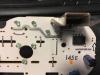
This should in principle be no problem. However, without knowing this specific PCB it is hard to tell whether these unpopulated pads (or lands as they are also called) are prepared to take the components required for the additional light/led.
These pads could be for an additional LED, they could be for an entirely other purpose as well.
I suggest you check the suitability of these lands:
- Measure the voltage between the two pads that are indicated by the two left arrows in the picture, i.e. the top pad of the supposed LED position and the bottom pad of the supposed resistor position. If you measure a steady DC voltage when the switch unit is powered, these pads could be suitable for the proposed purpose.
- It looks like there are pads for two resistors in parallel. This is not clearly visible in your image. Check whether the 2 top pads and the 2 bottom pads for the resistors are electrically connected in pairs. You may be able to see this by close visual inspection (if you see a copper trace between them) or by using a multimeter in Ohm range. If these pads are connected, then this is an indication that 2 parallel resistors should be used. This is to distribute the power dissipation.
- Check the pass voltage and the operating current of the LED you want to use (see the datasheet). From these values and the voltage measured in step 1 calculate the required series resistor as
Rtotal = (Vtotal - VLED)/ILED. I'd expect the result to be somewhere around 450 Ω.
Then use Rsingle= 2*Rtotal (910 Ω would be a good value if the previous result was ~450 Ω). By using 2 resistors in parallel the effective resistance is 1/2*Rsingle.
Observe the polarity of the LED. Other than an incandescent lamp an LED has a defined anode (+, long wire) and cathode (-, short wire). When reversed it will not light up.
When you encounter problems while proceeding as described above, come back here and report what you have achieved (and measured) so far, then we will try to guide you along.