Maker Pro
Maker Pro

Experiment with NPN transistor BC547

Hi
I am trying to switch on LED using transistor. I have a one BC547 transistor, potentiometer 470 ohm resistor and LED.

When I adjust pot LED doesn't turn ON What's wrong with connection?

bc457.jpg
 

bertus

Moderator
Hello,

Can you post a schematic, in stead of the breadboard?
Schematics are the universal electronic language.

Bertus
 

bertus

Moderator
Hello,

I hope you did not turn the potmeter fully to the +5 Volts.
If you did so, the transistor might not have survived the action and got burned out.
The base current may not exceed 20 mA.

Bertus
 

Attachments

  • bc547_ON.pdf
    72.8 KB · Views: 3

bertus

Moderator
Hello,

If you want to make better looking schematics, you can copy paste symbols from this sheet into your schematic drawing:
Electrical_symbols_library.png

Your schematic could look like this:

DJS_led.png


Bertus
 

bertus

Moderator
Hello,

No, the led is protected by the 470 Ohms current limiting resistor.
The transistor can be dameged by a to large base current.
When you put a resistor of 1K between the top of the potentiometer and the +5 Volts, the transistor is protected from a to high base current.
DJS_led base protected.png
Bertus
 
Hello,
When you put a resistor of 1K between the top of the potentiometer and the +5 Volts, the transistor is protected from a to high base current
Bertus
Hi
I want to perform experiment to see how the transistor work as switch. I have attached a circuit diagram
 

Attachments

  • IMG_20201101_205124.jpg
    IMG_20201101_205124.jpg
    166.8 KB · Views: 11
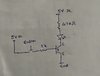
Your "transistor as a switch" circuit should work fine. Try it out!

One characteristic of transistors you should know about is that they have what's called "gain". Which means a small current flowing from base to emitter can control a much larger current from collector to emitter. The BC547 has approx 100-800x current gain, so you could use a much higher resistor on the base and the transistor will still turn on fully. For example, a 100K resistor would work, though 10K is more commonly used to ensure the transistor is fully "on" even if you're switching larger currents. For your little LED, a higher base resistor will work no problem.

With your circuit using a pot, you can see how the transistor responds over its "linear region" as well. This is the region in between "fully off" and "fully on". When the B-E voltage reaches 0.55V or so the junction starts to conduct and the transistor starts to turn "on". At around 0.7V it will reach saturation and be fully "on". This is a narrow range near the bottom travel of your pot, where it transitions between fully off, partially on, and fully on.

Since a transistor can control a much larger current using a smaller current, it works as an amplifier, like those in radios, cell phones, etc., and it can also be used to allow a small voltage/current to switch on/off a larger current.
 
You may instead do away with the pot and use a 10k resistor from collector to the switch and from the switch to the base. That should work as well.
 

Harald Kapp

Moderator
Moderator
use a 10k resistor from collector to the switch and from the switch to the base.
This will work but will not be efficient: When the transistor turns "on", Vce will fall towards 0 V thus reducing Vbe (via Rcb from collector to base). As the transistor needs Vbe = 0.6 V ... 0.7 V to turn on, Vce cannot fall below this value.
Better: Connect the resistor to V+ as shown by Bertus in post #9. Here the transistor can go into full saturation where Vce = 0.1 V (in the ballpark of), thus reducing power dissipation across the transistor and supplying 0.5 V ... 0.6 V more to the load.

In the case of a simple LED as load this may not have a noticeable influence at all as the load is small. But if you were to drive a high load through e.g. a power transistor, every millivolt counts. At a load current of e.g. 1 A (! the BC547 will not be able to drive this current!), a difference of 0.5 V in Vce results in 0.5 W power dissipation that would have to be taken care of.
This is one reason why Darlington transistors are not well suited to drive high current loads despite their high gain.
 
One more thing to add, if you dont put a resistor with the potentiometre, youll actually steal all the current from the collector as well, because itll short to the base.

And it definitely seems like a situation where the transistor would be fried.

But if the 2 5v entry points, where separate isolations, this current theivery actually doesnt happen, but u probably would have fried anyway.
 
if you have 2 isolated positives, (must go with) 2 isolated negatives. the current will add up on the lines, and they only short circuit within themselves.
To get an isolated pos+neg, you need a capacitor, a battery, or a transformer.
1 isolation, will only ever attract to itself, and 2 isolations can literally pass straight through each other (in a subtraction) and pop out the other sides full strength again.

If youve never known that your whole life, it may be a bit of a shock to you...
 
Top