First answers:
NC= Bauelemente werden nicht bestückt => component not used/assembled
NC=100pF bei Schwingneigung ... => use this 100pF capacitor only if ringing or oscillation occurs.
Use a housing with dimensions 120x93x31 mm³
Place the potentiometers in the top part of the housing.
Place input and output connectors to the left and right.
Place the switch with some distance to the lower edge of the housing so the 9V battery can be placed behind it.
Resistors you can
check yourself . E.g.:
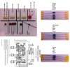
yellow/purple/black/orange/brown = 470kOm
If you try brown/orange/black/purple/yellow the calculator will tell you that it can't decipher the code.
By the way: It is a good idea to have at least a simple multimeter at hand to check e.g. resistor values, diode oriantation and solder joints. Or to search short circuits.
Capacitors:
brown round disc 101 = 10*10pF=100pF (10= 10, 1=10^1)
brown square discs 471 = 47*10pF=470pF (47=47, 1=10^1) = 470p on the PCB
brown square discs 392 = 39*100pF= 3900pF=3.9nF (39=39, 2=10^2)
white blocks .163 = probably 100nF/63V
white blocks 47n = 47nF = 0.0047on the PCB
white blocks 10n = 10nF = 10n on the PCB
white blocks .1K63 = probably 100nF/63V
Wima .1 = probably 100nF = 0.1 on the PCB
What irks me is
- there is a 3n3 capacitor on the PCB, but none of the capacitors in your photo seems to match that.
Diode 1N4001: cathode (-) is where the withe ring is on the plastic housing.
The PCB print is hard to read due to JPEG artifacts/low resolution. Next time please use higher res. pictures. And, if availabla, supply a circuit diagranm/schematic.
I hope that helps you along.
Haarld


