Sir donp . . . . .
O.K. then, with your board using the LM324, there are variants of that, and your board suggests of a 2008 vintage .
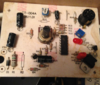
Take note of the power transformers 24 AC coming as the paired black wires to the right top corner of the pcb.
There the "cold" side of the AC supply routes to the left to become the AC and DC ground and the peripheral foil path drops on down for one portion of the AC for the soldering irons heater. The other AC line routes around the right periphery of the pcb to the TO-220 cased Triac, to selectively pulse power to the soldering irons heater.
The "hot" 24 Vac line also feeds into D1 diode to make you DC, and that DC then feeds into the pristine 150 2W metal film dropping / filter resistor and then into the closest BLACK E-cap and then there is being your missing R2 . . . a " twin " 150 2W metal film dropping / filter resistor . . . and it feeds into the lower, and further back, BLACK E-capacitor for even more filtering.
Then that supply line drops down to pin 4 . . . Vcc for your LM324.
As frugal as they were, I am seeing not even a trace of a 3 term regulator . . .or even a Zener diode placed on that supply.
So check that D1 diode to see that its not shorted as well as those 2 E-caps . . .
IF . . . . you find a shorted diode.
Since that specific situation seems to be the only reason for there being any suspicion of having problems with those two in series arranged resistors.
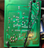
As per the boards appearance , the worst just seems to be the liberal use of flux on the connector and then a lack of its final clean up.
Did you check out your units heater element and the sensor . . . as I have shown on the inset, in
BLUE and
RED ?
PHOTO REFERENCING MARK-UP . . . . .
73's de Edd . . . . .
Almost everything in life is so much easier to get into . . . . . than to get out of.
.