Maker Pro
Maker Pro

Dpdt relay omron MY2N 240vac 24vdv

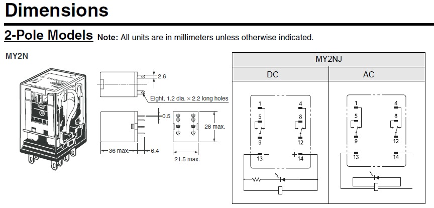
Hiya I am struggling with the above relay I don't know how to wire it I am just picking up electronics I have looked at the schematic drawings and because I am just learning I can't understand them . What I am trying to do is I have a extractor fan at home and I have been trying to fix a back draft type device to it ( a diy version ) . The idea is I connect this relay to the extractor fan so when I switch the extractor on power goes to the relay 240vac . I will have a permanent 24vdc supply to the relay that in turn will activate a actuator to raise a steel plate (diy back draft ) .when I switch the extractor off the reverse happens the steel plate will be lowered . Just like a sash window going up and down That is the plan the problem is I don't know how to wire the relay I know the coil is pins 13 and 14 so I will connect the positive and negative from the extractor fan motor to those pins . I am not sure please help me pins 9 and 12 are the pins for 24 vdc on to the relay .will someone please help and try to keep it as simple as possible as I am just learning thank`s again Keith.
 
Maybe draw a little schematic so we can see what you are trying to do.

I am no expert but from what I've seen dealing with these relays the 24VDC across the coil is the signalling circuit. Apply 24Vdc to it and the switch closes allowing the 240VAC to flow. The coil pins are normally 2 on their own on the one end of the relay
 

Harald Kapp

Moderator
Moderator
the 24VDC across the coil is the signalling circuit.
Not for this relay. Coil voltage is 240 V AV
Contact ratings are
AC: 220 V / 10 A
DC: 24 V / 10 A
Coil voltage (controlling the relay's operation) is between pins 13 and 14 (note that there is no plus or minus as this is AC voltage).
The contacts are arranged as:
contact 1: pin 9 = common, pin 1 = normally closed, pin 5 = normally open
contact 2: pin 12 = common, pin 4 = normally closed, pin 8 = normally open.
You connect the 24 V power to pins 9 and 12. You connect the load (actuator) to pins 5 and 8. Thus the actuator will be powered when the relay is activated by teh 240 V supply on the extractor being turned on.

One caveat: The actuator will be powered for the whole time the fan is on. Is the avtuator suitable for long term operation? If not, if it is only suitable for short term operation, you will need to add a limit switch whicl will turn off the actuator once the plate is open.
Plus some means to reverse the dirction of the actuator once the fan is turned off.
UNless all this is already provided for by e.g a gravity assisted closing of the steel plate ;)
 
Just wondering whether it is a good idea to have 240vac and 24dc on different contacts of the same relay.
A little too close together for my liking.
My preference would be two relays, one with 240vac contacts and the other with 24vdc contacts.
 

Harald Kapp

Moderator
Moderator
Just wondering whether it is a good idea to have 240vac and 24dc on different contacts of the same relay.
The 240 V are on the coil, 24 V on the contacts. That's what relays are made for.
It is not very common to have a relay operate with this setup of voltages (coil=high side, contact=low side), but it is completely viable.
 
This series can be AC or DC coil 24v - 240v
M.
920514959_727.jpg
 
Not for this relay. Coil voltage is 240 V AV
Contact ratings are
AC: 220 V / 10 A
DC: 24 V / 10 A
Coil voltage (controlling the relay's operation) is between pins 13 and 14 (note that there is no plus or minus as this is AC voltage).
The contacts are arranged as:
contact 1: pin 9 = common, pin 1 = normally closed, pin 5 = normally open
contact 2: pin 12 = common, pin 4 = normally closed, pin 8 = normally open.
You connect the 24 V power to pins 9 and 12. You connect the load (actuator) to pins 5 and 8. Thus the actuator will be powered when the relay is activated by teh 240 V supply on the extractor being turned on.s o

One caveat: The actuator will be powered for the whole time the fan is on. Is the avtuator suitable for long term operation? If not, if it is only suitable for short term operation, you will need to add a limit switch whicl will turn off the actuator once the plate is open.
Plus some means to reverse the dirction of the actuator once the fan is turned off.
UNless all this is already provided for by e.g a gravity assisted closing of the steel plate ;)
Thanks Harald spot on .The actuator has built in limit switches but has not arrived yet so can't give more details
24vdc on pins 9and 12 I thought so I must be learning something does it matter which way round ??.thanks again and everyone else for their help Keith.
 
Not for this relay. Coil voltage is 240 V AV
Contact ratings are
AC: 220 V / 10 A
DC: 24 V / 10 A
Coil voltage (controlling the relay's operation) is between pins 13 and 14 (note that there is no plus or minus as this is AC voltage).
The contacts are arranged as:
contact 1: pin 9 = common, pin 1 = normally closed, pin 5 = normally open
contact 2: pin 12 = common, pin 4 = normally closed, pin 8 = normally open.
You connect the 24 V power to pins 9 and 12. You connect the load (actuator) to pins 5 and 8. Thus the actuator will be powered when the relay is activated by teh 240 V supply on the extractor being turned on.

One caveat: The actuator will be powered for the whole time the fan is on. Is the avtuator suitable for long term operation? If not, if it is only suitable for short term operation, you will need to add a limit switch whicl will turn off the actuator once the plate is open.
Plus some means to reverse the dirction of the actuator once the fan is turned off.
UNless all this is already provided for by e.g a gravity assisted closing of the steel plate ;)
Thanks Harald would have struggled without your help thank's for your time keith
 

Harald Kapp

Moderator
Moderator
does it matter which way round ?
No, it doesn't.

Will the actuator return to the rest position once you remove power (24 V)? If not, you may need to modify teh circuit such that the power is reversed when the fan is turned off. This can be achieved with the same relay in a slightly different connection scheme:
upload_2016-12-8_7-36-2.png
Here the polarity of the 24 V DC to the actuator is reversed by the action of the relay, which may be just what you need.
 
No, it doesn't.

Will the actuator return to the rest position once you remove power (24 V)? If not, you may need to modify teh circuit such that the power is reversed when the fan is turned off. This can be achieved with the same relay in a slightly different connection scheme:
View attachment 30784
Here the polarity of the 24 V DC to the actuator is reversed by the action of the relay, which may be just what you need.
 
I'm still waiting for the actuator so I only know it has built in limit switches . I think you reverse the current to get the actuator to close hence the need for the dpdt relay .i will get in touch if I get stuck thanks again Keith
 
Top