I've planned out an FM scanner that I'm going to build, but I'd like to have someone eyeball it first to make sure I'm not going to waste a lot of time on something silly. I'm more of a digital fellow, and analog is relatively new to me.
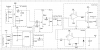
Anyway, how I intend this circuit to work is I have a voltage from a DAC to signify the frequency to tune to. This goes to a LTC6905 acting as a VCO (I copied this out of the docs for it), which then goes to a JFET mixer. The other input to the mixer is from the antenna, followed by a high pass filter and a
JFET amp. Then, I filter to get the audio component, and then I branch that off.
One side goes to a simple inverting amplifier with a push-pull output then headphone jack, and the other goes to an active rectifier, which then gets smoothed with a cap, which goes to an ADC for the digital bits to be a measure of signal amplitude.
Does this seem reasonable? I'm fairly confident in the opamp bits, and the LTC6905 (since it is straight from the app notes), but JFET's seem rather unpredictable to me.
Thank you for your help.
")