Hi guys,
First of all I'd like to say that I have seen the same or similar questions asked in many forums but nobody has ever come up with a concrete solution or posted anything about the results of trying out the various suggestions given to them. So here I am still trying to figure things out so please help me out. And now to my problem
I am planning to proportionally drive a solenoid of the following specs: 24VDC,1.19A 28.5W resistance 20.2ohms +-5% at 20C
I'm planning to use the arduino to accomplish this. I'm aware of the whole concept of dither which is necessary to avoid stiction in the solenoid valve. As most of you will be aware of, we cannot freely choose the pwm frequency in the arduino but are restricted to a few discrete frequency values of which only 30.5Hz (Pin 3,9,10,11), 61Hz (pin 5,6) and 122Hz (Pin 3,9,10,11) are below 200Hz. I found optimal dither at 122Hz which is okay. ( A tiny part of the project is taken care of)
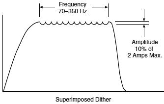
But I can't use the the dither signal alone to drive the solenoid due to obvious reasons as it is not possible for the dither signal to form a constant amplitude since the PWM frequency has to be continuously adjusted as a function of the stipulated desired current value and in the process the amplitude and the frequency of the dither will signal change accordingly. In other words i need the dither to be a constant while i'll still be able to change the average current in the solenoid to manipulate the spool proportionally.
Then I stumbled upon a concept of superimposing the dither ( low frequency signal ) on a high frequency PWM signal.

But i do not know how to do this. Some smart guy by the name of Drazzy suggested in an old arduino forum :"You could put source of a small MOSFET on one pin, and gate on the other....". If i got him right he means using one MOSFET at a lower frequency to switch another MOSFET at a higher frequency (or the other way around? i'm confused:| ).
I also came across a website that talked about combining PWM outputs. http://www.openmusiclabs.com/learning/digital/pwm-dac/dual-pwm-circuits/
Is there anyway that i can use this in this application in context?
Either way could someone shed some light on this. will this work practically? what would be the circuit like? Any useful information is welcome. Any other ways to achieve the same are also welcome.
Help a friend and thank you in advance
First of all I'd like to say that I have seen the same or similar questions asked in many forums but nobody has ever come up with a concrete solution or posted anything about the results of trying out the various suggestions given to them. So here I am still trying to figure things out so please help me out. And now to my problem
I am planning to proportionally drive a solenoid of the following specs: 24VDC,1.19A 28.5W resistance 20.2ohms +-5% at 20C
I'm planning to use the arduino to accomplish this. I'm aware of the whole concept of dither which is necessary to avoid stiction in the solenoid valve. As most of you will be aware of, we cannot freely choose the pwm frequency in the arduino but are restricted to a few discrete frequency values of which only 30.5Hz (Pin 3,9,10,11), 61Hz (pin 5,6) and 122Hz (Pin 3,9,10,11) are below 200Hz. I found optimal dither at 122Hz which is okay. ( A tiny part of the project is taken care of)
But I can't use the the dither signal alone to drive the solenoid due to obvious reasons as it is not possible for the dither signal to form a constant amplitude since the PWM frequency has to be continuously adjusted as a function of the stipulated desired current value and in the process the amplitude and the frequency of the dither will signal change accordingly. In other words i need the dither to be a constant while i'll still be able to change the average current in the solenoid to manipulate the spool proportionally.
Then I stumbled upon a concept of superimposing the dither ( low frequency signal ) on a high frequency PWM signal.

But i do not know how to do this. Some smart guy by the name of Drazzy suggested in an old arduino forum :"You could put source of a small MOSFET on one pin, and gate on the other....". If i got him right he means using one MOSFET at a lower frequency to switch another MOSFET at a higher frequency (or the other way around? i'm confused:| ).
I also came across a website that talked about combining PWM outputs. http://www.openmusiclabs.com/learning/digital/pwm-dac/dual-pwm-circuits/
Is there anyway that i can use this in this application in context?
Either way could someone shed some light on this. will this work practically? what would be the circuit like? Any useful information is welcome. Any other ways to achieve the same are also welcome.
Help a friend and thank you in advance
