Hello again guys, I have completed the question attached and also included the workings, but there are a couple of aspects to it that I just cant seem to understand, and was hoping you would be able to help me with.
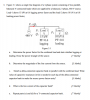
The first part is in the first question, and it is how we are able to tell the Q1 is being absorbed and Q2 is being injected. Is this due to the fact the load 1 is lagging, so its reactive power must be being absorbed, and load 2 is leading so its reactive power is being injected?
For the second question, where has the equation for the apparent power come from? I understand the apparent power is equal to voltage multiplied by current, but why also multiplied by the square root of three? Is this due to the loads being Y-connected and making the equation for Vline be the voltage multiplied by the square root of three?
This pretty much sums it up, on a side note, I am having difficulty of understanding how the capacitor banks work so if somebody would be able to put some clarification down, I would be very grateful. As always, thanks for any help and if I missed anything out please let me know.