Maker Pro
Maker Pro

Converting Russian Calculator to 9v DC

Hi,

I'm new to electronic modding so I hope I'm not out of place posting here. I am looking for some help to identify some of the wires and parts in this calculator, which is a Soviet made Elektronika MK59 (mid eighties) in order to try and convert it from ac 220v to something dc 9v battery based. That's the hope anyway, I don't even know if it's possible with this device. The calculator does work via mains power.

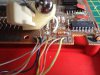
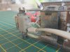
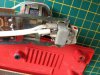
I've attached several pictures of the internals, notably the wires going in and out of the power transformer inside and where they attach to the board.

Thanks for reading
Jon

attachment.php


attachment.php


attachment.php


attachment.php


attachment.php
 

Attachments

  • IMG_0002.jpg
    IMG_0002.jpg
    42.2 KB · Views: 200
  • IMG_0007.jpg
    IMG_0007.jpg
    55 KB · Views: 163
  • IMG_0008.jpg
    IMG_0008.jpg
    38.6 KB · Views: 198
  • IMG_0009.jpg
    IMG_0009.jpg
    43.3 KB · Views: 189
  • IMG_0010.jpg
    IMG_0010.jpg
    77.1 KB · Views: 179
Last edited by a moderator:

(*steve*)

¡sǝpodᴉʇuɐ ǝɥʇ ɹɐǝɥd
Moderator
Whilst I wouldn't say it's impossible, it's probably very close to it.

If you could get ti running from a 9V battery the lifetime would probably be measured in tens of minutes.

The display requires quite a high voltage, it could be around 90V.

If that was in my calculator collection, I wouldn't risk damaging it.

Thanks for the advice.

--Jon
 

Fish4Fun

So long, and Thanks for all the Fish!
@==>*steve*

Why would you say the display might require 90V? It appears to me to be an LED display and while I am not any kind of expert on displays, I have never encountered an LED display that required more than 12V. The fact that there are 7 wires leading from the PS board to the main board certainly suggests a more complex supply than I would have thought were required, but the transformer secondary appears to be a simple center-tapped design; and I would guess from the vintage if a HV rail were required it would have been achieved by a third winding on the transformer. It does appear that two white wires run directly from the primary side to the PS board, and I cannot even begin to explain why they would be there; so all of this is conjecture on my part, I don't have a calculator collection ;-) but I am intrigued both by your assertion that the display might be HV, AND the fact that there are 7 wires running from the PS board to the main board.

PLEASE expound a bit on your thoughts/experience with vintage calculator designs; I am not questioning you, only very, very curious. By the mid 1980's SMPS power supplies were certainly available, but were not common (to my knowledge) in anything other than PCs and a select few audio amplifiers, but I guess it is possible the transformer is being switched not line driven, but that seems awfully complicated for a calculator of that period.

Again, please expound a bit!

Fish
 
It is a vacuum fluorescent display, and while most modern ones do have onboard converters to step it up to the appropriate voltage, this board appears far too simple in construction - likely there is a higher-voltage tap on that transformer that is feeding it.

That being said, it is in the realm of feasibility to construct a 220V step-up inverter, possibly being fed from a 9.6V high-capacity rechargeable, and using that - that way the original circuit would require absolute minimal modification. However, as Steve said, the battery life most certainly would not be stellar.
 

Fish4Fun

So long, and Thanks for all the Fish!
@Solidus==> Thanks, those are VERY cool! I was completely unaware of that technology, so of course I had to go order a few for my display collection :) Now if I could just find something that needed a display....hehe.

Fish
 
Thats a nice piece of kit - probablt worth a few bob now. Personally I wouldnt risk damaging it, but if you really want to, I would suggest plugging it in and (carefully) measuring the voltages at key points which would be across the transformer output and the display - Its just a matter of taking a methodical approach and figuring out what needs done at each point
 
Top