Maker Pro
Maker Pro

Confusing waveform driving PC speaker.

I have a circuit that generates a nice square wave of about 5V p-p balanced about zero volts.
However when I connect a small PC speaker of 8 ohms to it, the waveform changes to a series of spikes. Can someone explain why this is happening?

I have attached scope images showing the waveforms as well as the circuit diagram.
 

Attachments

  • AmpX1.png
    AmpX1.png
    3.4 KB · Views: 135
  • AmpX3Waveform.pdf
    12.4 KB · Views: 116
  • AmpX4Waveform.pdf
    13.4 KB · Views: 123

davenn

Moderator
just a wild guess.... ;)

probably the effect of those 2 caps you have in the circuit

why have you got them there, they serve no useful purpose ?
try without them

Dave
 

KrisBlueNZ

Sadly passed away in 2015
C1 and the resistance of the speaker are acting as a "C-R differentiator"

This circuit is described at http://en.wikipedia.org/wiki/Passive_differentiator_circuit but this description immediately jumps into heavy maths, so unless you're a mathematician or physicist, don't bother with it.

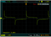
In short, when the time constant of the capacitor and the resistor is small compared to the period of the square wave, the differentiator will turn the signal into a series of positive-going and negative-going spikes. If you want to avoid this, you need to increase the time constant so it's significantly greater than the period of the waveform.

The time constant is the capacitance (in Farads) multiplied by the resistance (in ohms). The answer is in seconds. With C1 = 0.1uF and R = 8 ohms (I will assume), T = 0.1e-6 * 8 which is 0.8 microseconds. The period of an 18 kHz waveform is 56 microseconds. So you need to increase the time constant by a factor of about 70. Increase C1 to at least 7 uF and the problem should get better. Increase C1 even more, and the curves in the waveform you see across the speaker will eventually go away.

This change will increase the loading on the output of your frequency source. This will probably affect the waveform at its output. You may need to insert a buffer of some kind between the frequency source and C1.

Inserting a series resistor of, say, 100 ohms will improve the waveforms and reduce the loading on the frequency source, but will greatly reduce the amount of energy at the speaker.

Using a speaker with a higher resistance, e.g. 32 ohms, and/or a matching transformer, will help.
 
Last edited:
I probably should explain...
The 820pf cap cuts out the rather large overshoot that comes directly out of the oscillator module at 18 KHz.
The 0.1uf cap blocks the DC component of the module output.
Without the speaker being connected, the output is a nice clean square wave centered at zero volts and amplitude 5V p-p.
With the speaker connected the result is the spikey waveform. I know the speaker is an inductor, but the spikes look like its a capacitive load and not an inductive one.
 
The time constant is the capacitance (in Farads) multiplied by the resistance (in ohms). The answer is in seconds. With C1 = 0.1uF and R = 8 ohms (I will assume), T = 0.1e-6 * 8 which is 0.8 microseconds. The period of an 18 kHz waveform is 56 microseconds. So you need to increase the time constant by a factor of about 70. Increase C1 to at least 7 uF and the problem should get better. Increase C1 even more, and the curves in the waveform you see across the speaker will eventually go away.

This change will increase the loading on the output of your frequency source. This will probably affect the waveform at its output. You may need to insert a buffer of some kind between the frequency source and C1.

Inserting a series resistor of, say, 100 ohms will improve the waveforms and reduce the loading on the frequency source, but will greatly reduce the amount of energy at the speaker.

Using a speaker with a higher resistance, e.g. 32 ohms, and/or a matching transformer, will help.
- Yes, I understand about the time constant.
- What kind of buffer are you thinking about? An inverter would get rid of the overshoot, and so omit the need for the 820pf cap. But I need something to block the DC component before it goes to the speaker.
- I'll try to find sources for the 32 ohm speaker and transformer

I do have a rather large Sony audio amplifier, but what input do I use? Aux?
 

KrisBlueNZ

Sadly passed away in 2015
If you "understand about the time constant" then you should know the reason for the "spiky" waveform. The time constant of 0.1 uF and 8 ohms is 0.8 microseconds, and the period of your waveform is 56 microseconds. So the signal you see across the speaker will be one positive and one negative spike every 56 microseconds, with each spike falling from its peak voltage to the 37% "1T" point in about 0.8 microseconds. That's why you see that waveshape.

I'm not suggesting adding an inverter gate, or any other kind of gate. You need a buffer with a low output impedance if you want to drive an 8 ohm (or even 32 ohm) speaker directly. The other option, as I mentioned, is adding a series resistor, but this greatly reduces the amount of power available at the speaker.

You can make a simple buffer for a digital signal from two transistors connected as an unbiased class B output stage. You'll lose about 1.4V p-p from your signal, so it will drop to about 3.6V p-p. You still need a DC blocking capacitor in series with the speaker, but you can use one with a much higher value - say 100 uF. That will eliminate the "spiky" effect.

Look at http://www.electronics-tutorials.ws/transistor/tran_3.html under the heading "Transistor Matching" to see how the two transistors should be connected. You only need two transistors, and a DC blocking capacitor. You may want to keep your 820 pF capacitor across the 18 kHz signal, if there really is overshoot on that signal. (It could just be an incorrectly compensated scope probe.)

Using a proper amplifier may be a good idea. Will it drive the speaker you need to use? Yes you should use the Aux input. You will probably need to attenuate the signal from your oscillator using a voltage divider, otherwise you and your amplifier will be in for a nasty surprise when you connect it up. You may also want to monitor the amplifier output voltage with an oscilloscope to avoid overdriving it; with an inaudible signal, it's easy to overdrive the amplifier and you might damage it.

What is the purpose of all of this? What is significant about 18 kHz?
 
@KrisBlueNZ
The 18 KHz is my choice. We can reduce it to say 9 KHz so can hear it.

Let's go with the Sony amp. What's the typical limit for the input signal?
The amp gives 50 watts per channel, so it should rive anything.For now the PC speaker will do. What do I use for DC blocking on the aux input?
 

KrisBlueNZ

Sadly passed away in 2015
You haven't answered my main question: what is the purpose of all of this?
I'm not trying to be nosey. Knowing more about what you want to do may help us give you better advice.

I don't know what the specified input voltage for the Aux inputs is. It might be listed among the specifications in the user manual for the amplifier. Line-level inputs commonly want a signal around 200~500 mV RMS. That's about 500~1500mV peak to peak.

I would feed the signal generator output through a DC blocking capacitor (0.1 uF will be OK here because the load resistance is relatively high), then through a 100K resistor, to one end of a potentiometer or trimpot, whose other end is grounded. You feed the amplifier from the wiper of the pot/trimpot and common the grounds together.

If you use a potentiometer, get a logarithmic one. If you use a trimpot, you'll have to use a linear one, because AFAIK you can't get logarithmic trimpots. Set the trimpot to minimum and the amplifier gain to minimum before you start.

Edit: Try a potentiometer or trimpot value of 10k first. This will allow you to adjust the output signal level from zero to 450 mV peak to peak.
 
Last edited:
@KrisBlueNZ
I just wanted to create a variable freq. signal generator. I chose 18KHz as a first target, not knowing that I might not hear it. The oscillator module generates good square waves well past 68Mhz, and I may try this circuit up to that freq. The speaker was just a convenient test device. Once I get it working I may connect the output to other devices.

I tried raising the blocking cap to 100uf (in series with the speaker) but it didn't change the waveform much at all. Even with 10uf, the time constant should have gone to 80 microseconds and I didn't see anything that long. There must be something else to this. I attached a waveform PDF for the 100uf cap.)

I tried all this before with the same results and that's why I asked here.
 

Attachments

  • 18KHz100ufwaveform.png
    18KHz100ufwaveform.png
    43.9 KB · Views: 110

KrisBlueNZ

Sadly passed away in 2015
You changed the DC blocking capacitor from 0.1 uF to 100 uF without making any other changes, and still got the same waveform across the speaker?

What are the characteristics of the frequency generator? It may have a coupling capacitor in it as well.

At the least, we need to see the schematic of the frequency generator, and exactly how you have connected it to the speaker.

It would probably save a lot of back-and-forth if you posted ALL the information you have on everything.

Try using the two-transistor buffer I suggested earlier. Check the waveforms on the input and output of the buffer, and across the speaker.
 

davenn

Moderator
@KrisBlueNZ
I just wanted to create a variable freq. signal generator. I chose 18KHz as a first target, not knowing that I might not hear it. The oscillator module generates good square waves well past 68Mhz, and I may try this circuit up to that freq.

well thats pretty pointless for an audio sig generator

and that 68MHz ISNT going to be a fundamental freq as there aren't too many opamps that would operate at that freq they will just be harmonics

Square wave oscillators are harmonic rich and definately not usually what you need for audio testing
You need a sinewave osc that covers ~ 100Hz to ~ your original 18kHz


The speaker was just a convenient test device. Once I get it working I may connect the output to other devices.

I tried raising the blocking cap to 100uf (in series with the speaker) but it didn't change the waveform much at all. Even with 10uf, the time constant should have gone to 80 microseconds and I didn't see anything that long. There must be something else to this. I attached a waveform PDF for the 100uf cap.)

I tried all this before with the same results and that's why I asked here.

time for you to google audio oscillator circuits, there's lots out there ... fixed and variable freq :)

Dave
 
You changed the DC blocking capacitor from 0.1 uF to 100 uF without making any other changes, and still got the same waveform across the speaker?

What are the characteristics of the frequency generator? It may have a coupling capacitor in it as well.

At the least, we need to see the schematic of the frequency generator, and exactly how you have connected it to the speaker.

It would probably save a lot of back-and-forth if you posted ALL the information you have on everything.

Try using the two-transistor buffer I suggested earlier. Check the waveforms on the input and output of the buffer, and across the speaker.
Hahaha! Yes, the circuit is the same except for the chnage from 0.1uF to 100uF.
As for the info, I sent about all I have. You can see the oscillator module here http://www.gravitech.us/i2c1kto68pro.html and download the user manual, but it has no schematic. I have tried unsuccessfully to get them to send me the schematic, so I assume its proprietary. The chip it uses is the LTC6904. Its datasheet may tell you more, but I don't have enough experience to pick out what you might need to know. And I gave you a diagram of my circuit in the first post.

As for the parts for the buffer, it will take a month to get them, so if the audio amp will work, I'll use that. I'll have more confidence if we can resolve the reason for the poor waveform.
 
Last edited:

davenn

Moderator
OK on the osc link looks nice :)

BUT I think its time for you to define what you are trying to do

That unit is an RF oscillator

is that what you really want or are you really wanting an audio oscillator for testing sound gear etc?

the diagram in your first post is pretty irrelevent for this particular osc..... You DONT really want to be feeding it into a speaker

As I said you really need to define what it is that you are attempting to do

Dave
 
Last edited:

KrisBlueNZ

Sadly passed away in 2015
Thanks for the link. You should have included that with your first post.

You should also have told us what you are trying to achieve. So far, all I've been able to tell is that you're just experimenting and seeing what the oscillator module is capable of. Is that right? There's nothing wrong with admitting that you're just mucking around. But we need to know what you're trying to achieve. Really, we do.

The outputs from the oscillator board appear to come from pins 5 and 6 of the LTC6904 via 24.9 ohm resistors. These output pins are NOT designed to drive a speaker directly. You CAN use a two-transistor buffer as I described in post #6 in this thread. If you couple this buffer to the speaker using a 100 uF capacitor you should see a reasonably accurate square wave at the speaker - at high audio frequencies at least. At lower frequencies you need to increase the capacitor. 1000 uF should be enough to give a reasonable square wave at frequencies down to 1 kHz.

This partly depends on the impedance of the speaker, which you have not told us. This would be useful information.

Alternatively you can connect the output to your audio amp as I described in post #8 on this thread. I've just edited it to include a suitable value for the trimpot - 10 kilohms. If you can't get hold of a 10k trimpot, just use a voltage divider using two fixed resistors:

LTC6904 output ------| |-------\/\/\/\/-----------\/\/\/\/--------GND
. . . . . . . . . . . . . . 0.1uF . 100k . . | . . . 10k
. . . . . . . . . . . . . . . . . . . . . . . . . . ----------------> to amp input - signal
GND-------------------------------------------------------------> to amp input - ground

Check the waveforms with either (or both) of these circuits. You should see a fairly clean square wave at all points.

BTW you have been a lot less than forthcoming on this thread. You only posted a link to the module on post #12 in this thread; it should have been in post #1. We don't do industrial espionage here; don't treat your project like a state secret, and don't feel afraid to burden us with unnecessary information. You may not know what's important and what isn't, so you should give us as much relevant information as you can.

While you're at it, it can be helpful if we know where you're located. This is not so that we can send spies out to monitor your confidential cutting-edge experiments; it affects our component and company recommendations.
 
Last edited:
Top