Maker Pro
Maker Pro

Confusing Relay-Relay Connection .. pls help

hi everyone kindly see my setup doc below ! tnx !
is the actual setup going to be OKAY ???
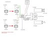
actually it worked, and still working since the last 4 days .. I want to energize the relay whenever EACH or BOTH of the devices closes contact ....

but i think the devices' internal contacts are not carrying both the load of the relay, i think it is only carrying the power supply (12V 1A) intended for the dpdt relay ONLY sir if i'm not mistaken . because the internal contacts of the device can only handle 15W contact rating, whereby the 2 output devices are rated at a total of 22W ... i'm triggering the internal contacts of the devices for more than 10 times a day , and nothing bad happens ...

i just want to know if it will last long without future troubleshooting .. but there will be of course as time goes by . and i also want to know where are these potential spots that will need troubleshooting in the future . tnx
 

Attachments

  • the setup.jpg
    the setup.jpg
    69.8 KB · Views: 1,151

Harald Kapp

Moderator
Moderator
This looks totally fine.
The receivers only supply the current to the relay coil, this is typically much less than 15W.
 

KrisBlueNZ

Sadly passed away in 2015
The only mistake is the lack of back EMF suppression on the coil of your 5A DPDT relay. This is unlikely to be a problem because these relays will not be activating very often, but I will mention it for completeness.

When the contact closes on a receiver, a circuit is completed and 12V is applied to the coil of your 5A relay. When that contact opens, the coil will generate a large voltage spike called "back EMF" as the current in the circuit tries to stop flowing. This voltage spike can cause arcing in the contact on your receiver, and eventually this will damage the contact. This back EMF can be avoided simply by connecing a diode (e.g. 1N4001) across the coil of the 5A relay, with its anode to the negative side ('GND' on your drawing) and its cathode to the positive side (the side that connects to the top junction box).

Here are some other suggestions.

1. You have a total of seven "12V adapter" positions shown on your diagram. You actually only need one adapter, provided that it can supply enough current for everything. Probably a 12V DC 3A adapter would be fine.

2. There is no need to switch the siren and the LED through separate contacts. You can just connect the LED directly across the siren.

3. If this is a critical alarm, you can gain some security by using a "fail safe" loop between the receivers and the 5A relay. This involves using a normally closed circuit path, instead of a normally open circuit. Since the most common failures involve breaks in the circuit (wire pulled out of connector, wire crushed, etc), with a normally open circuit, a failure will most likely prevent the alarm from operating at all. And you won't know about the failure when it happens.

If you make the loop normally closed, if a break occurs, the alarm activates immediately and you know there is a problem.

The changes to the circuit are:
(a) use the normally closed contacts of the receivers;
(b) connect the contacts in series instead of in parallel;
(c) use the normally closed contact of the 5A DPDT relay.

The system could be made even more reliable if the receivers had fail-safe operation. As it stands, if power is lost to a receiver, the alarm will not activate. But if the receiver doesn't have that feature, my description above is the best you can do.
 
Hi sir kriz,
1. why do i need to connect the receivers' contacts in parallel ?
2. aren't the siren and the lights be turned always on if i use the normally closed loop?
3. Can i use 1N4002 diode instead of 1N4001 ?

and where will i specifically connect the anode and cathodes of the diode sir ?
 
Last edited:

Harald Kapp

Moderator
Moderator
1) in your circuit the contacts are in parallel. Kris suggests a completely different setup by putting the contacts in series and using another set of contacts from the relay to drive the siren and light. Re-read Kris' post, he explains it fairly well. The principle is also described here.
2) That is why you use the normally closed contacts. Note that in order for this to work your receivers need to have a normally closed contact (currently you are using the normally open contact of the receivers).
3) 1N4002 is fine. You connect the diode across the relay coil, Anode to GND, Cathode (where the ring is on the diode's case) to +12V. Note that the diode will not conduct in this orientation. It is there to prevent a negative voltage on the coil's connectors which will arise due to induction when the relay is turned off.
 
Hi again sir Herald, i just talked to the supplier of that relay, he told me that there is no need for a flywheel diode since the relay is powered only at 12V DC 1A supply , and even its loads are only
Terminal 1: 4pcs 28Vdc 7W LED pin light connected in parallel
Terminal 2: 12 Vdc 15W Siren

....
what do u think sir ?
 

KrisBlueNZ

Sadly passed away in 2015
Hi again sir Herald
Sir Harald is away at his castle, hunting foxes and talking to his subjects. But Sir Kris can answer your question. ;-)
i just talked to the supplier of that relay, he told me that there is no need for a flywheel diode since the relay is powered only at 12V DC 1A supply , and even its loads are only
Terminal 1: 4pcs 28Vdc 7W LED pin light connected in parallel
Terminal 2: 12 Vdc 15W Siren
He's wrong. Perhaps he doesn't understand the question. You should have a back EMF suppression diode across the coil. A relay coil is inductive. When current to the coil is interrupted, it generates an inductive kick-back, also called back EMF or flyback voltage, that can cause arcing in the contacts of the relay (inside the receiver) that are trying to open to break the circuit. This back EMF should be suppressed with the addition of a diode across the relay coil.

There's no reason to talk to your relay supplier about this anyway. Just get a diode and put it there. Most silicon diodes are suitable. I suggest a 1N4001/2/3/4/5/6/7.
 
and lastly sir, i just want to be specific, can u help me choose the BEST and suitable diode among 1N4001 to 7 ? we are about to put this setup to a large-scale community project ,,!
 

KrisBlueNZ

Sadly passed away in 2015
They are all equally suitable. Buy whichever one is cheapest, or is already used in another part of the project.

BTW I was kidding about the "Sir" bit. Neither Harald nor I are old enough, rich enough, or noble enough to be called "Sir" :) You don't need to use that word.
 
and another thing sir , in that setup I diagrammed HERE BELOW , whenever the receivers are triggered, of course the 3PDT relay is energized, but the behavior of the LED indicator seems to be different in the normal testing of a relay wherein we just connect the relay to a power supply . here's what's happening :

at the actual setup:
- whenever the receiver contacts are triggered, the 3PDT relay is also triggered but the LED indicator just turns on for less than a second and then turns off , BUT THE 3PDT RELAY IS STILL ENERGIZED AND OUTPUTS ARE STILL POWERED ON (knowing that receiver contacts are still triggered)

at the testing
- whenever i connect the 3PDT relay's 2 coil terminals directly to its power supply , the relay is of course energized AND THE LED INDICATOR IS TURNED ON AS LONG AS the 3PDT relay is still connected to the power supply ....

why do u think is this happening sir ?
 

Attachments

  • ELECTRONICS HELP.jpg
    ELECTRONICS HELP.jpg
    91.7 KB · Views: 236

KrisBlueNZ

Sadly passed away in 2015
So you're saying that when the 3PDT relay coil is energised through the receivers, the built-in LED indicator turns on for a second then goes out, although the lamp and the siren keep going?

And when the 3PDT relay coil is energised directly from a 12V supply, the built-in LED indicator works as it should?

With the receivers driving the 3PDT relay's coil, measure the voltage across the coil. Check that this voltage goes to 12V when the receiver output turns ON, and that it remains steady. Check that the polarity is right.

What is the manufacturer's name and the part number for the relay? Can you post a link to a data sheet for it? If there is no data available, can you post a link to the auction?


yes sir the polarity is correct, the voltage is a steady 12V when receiver output is on .

the relay is an OMRON MY3NJ 3PDT 12V 5A RELAY . I just bought it in a local electronics store . here's the pix and a close link
actually the coil inside indicates a 12VDC mark
the indication outside the coil (written in the blue box) is
5A 240VAC
5A 28VDC

and i'm supplying it with a 12V 1A adapter and runs good when coil terminals and adapter are connected directly .

http://www.ebay.com/itm/OMRON-MY3NJ-DC-12V-11PIN-Power-Relay-/330444710565
 

Attachments

  • IMG_1613.JPG
    IMG_1613.JPG
    86.2 KB · Views: 141
  • IMG_1614.JPG
    IMG_1614.JPG
    109.7 KB · Views: 167

KrisBlueNZ

Sadly passed away in 2015
I can't find a data sheet for the MY3NJ; only for some versions of the MY2 and MY4.

I don't know what's wrong. My guess is that you're connecting something wrong but I don't know for sure. I suggest you try a different relay.
 
ok sir, if I already connected a 1N4002 or 7 (because those are the only diodes i have ) diode across the coils of the relay , how can I know or measure that the setup is already good/safe from back emf?
 

KrisBlueNZ

Sadly passed away in 2015
As long as the diode is new and is reliably connected across the coil, you should be fine.

If you really want to test it, you could connect an LED across the relay coil with the same polarity as the diode. That is, anode to negative and cathode to positive. Then activate an alarm to close the relay, and deactivate it so the relay opens. Watch the LED as the relay opens (preferably in a dark room). If there is a visible blink from the LED, then the diode is faulty or not properly connected.
 
Hi Sirs, here's a clearer diagram of the actual relay . here's the LEd i'm telling you ..

and by the way sir, I had already fixed the sudden turning off of the LED indicator, it's now working just fine .
 

Attachments

  • New Relay.jpg
    New Relay.jpg
    9 KB · Views: 163

KrisBlueNZ

Sadly passed away in 2015
Good. So you need to connect your 1N4002 or 1N4007 across the coil pins, in the opposite direction to the LED inside the relay.

So everything is working now?
 
Top