Hello All,
I was hoping someone would be able to assist with development of this circuit I am trying to replicate on a breadboard as a test
http://www.zen22142.zen.co.uk/ronj/rt2s.html
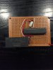
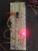
I have attached a photo but it will probably be too hard to see anything of use on it.
Basically, it doesn't really do anything. Occasionally touching components, or moving my hand around it can turn it on and off. So I have something floating although I don't think that explains why it's not cycling itself.
One difference is that I had to go with the two 1000uf caps back to back as I couldn't get a non-polar one at the required rating.
Does anyone have any pointers as to what I can look for to figure out what is going on?
I am also open to any other circuit suggestions. I'm after switching on a relay for 30 seconds every 15 minutes. I looked at 555 timer but the advice seems to be it's not really suited for longer timeframes.
Edit: I found one issue. It no longer turns on and off from touching it. It just stays constantly on now though.

I was hoping someone would be able to assist with development of this circuit I am trying to replicate on a breadboard as a test
http://www.zen22142.zen.co.uk/ronj/rt2s.html
I have attached a photo but it will probably be too hard to see anything of use on it.
Basically, it doesn't really do anything. Occasionally touching components, or moving my hand around it can turn it on and off. So I have something floating although I don't think that explains why it's not cycling itself.
One difference is that I had to go with the two 1000uf caps back to back as I couldn't get a non-polar one at the required rating.
Does anyone have any pointers as to what I can look for to figure out what is going on?
I am also open to any other circuit suggestions. I'm after switching on a relay for 30 seconds every 15 minutes. I looked at 555 timer but the advice seems to be it's not really suited for longer timeframes.
Edit: I found one issue. It no longer turns on and off from touching it. It just stays constantly on now though.
Attachments
Last edited by a moderator: