Maker Pro
Maker Pro

Circuit does not simulate

Hi,

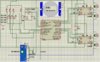
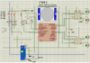
I tried to run this circuit (simulation) but it does not seem to run.

i haven't done the program yet, there are 4 buttons each of them change the mode on how the motor operates, e.g if button 1 is pressed the motor will all run at the same time but if button 2 is pressed then 2 of the motor will run separately to the other two.

this is a reciever circuit, i am yet to make the transmitter circuit, the aim of this is to make a orb/ball controlled by a remote control.
 

Attachments

  • Circuit A.png
    Circuit A.png
    79.9 KB · Views: 17
  • Circuit b.png
    Circuit b.png
    125.4 KB · Views: 12
  • error message after sim.png
    error message after sim.png
    18.1 KB · Views: 11
Last edited:

Harald Kapp

Moderator
Moderator
The image is hard to decipher, letters almost unreadable. Please upload an improved image.
A few more details, please:
  • What is the circuit supposed to do?
  • What is the simulation result instead?
  • Are there any error messages you can communicate?
 
Thanks for your reply, i couldn't get a better as i tried to scrreen shot them and they came out similar but i did try to get the values so you could see them, hopefully this is ok but if this is not enough can let me know?

I tried to screen shot the motor driver and microcontroller so you could see them. I am not used to uploading images, for better quality if you have any suggestion i'll follow them through.
 

Attachments

  • Circuit A.png
    Circuit A.png
    107.9 KB · Views: 18
Last edited:
Probably a bit late on this but anyway...

Your crystal caps (C1 and C2) would usually be connected to DGnd (Digital Ground).
Could be that the simulator doesn't let the crystal startup.
Also don't see any power connections to your cpu.
 
Probably a bit late on this but anyway...

Your crystal caps (C1 and C2) would usually be connected to DGnd (Digital Ground).
Could be that the simulator doesn't let the crystal startup.
Also don't see any power connections to your cpu.

It's never too late and thank you for your reply,

I connected the (Pin 1) Vpp to 12 volts and connected the Crystal Capacitors to ground but the results continue to remain the same (does not simulate).

Is there anything else that could help?
 
Hi, I'm not familiar with the simulator so cannot give you an exact solution.
Best is to try anything/everything that you have tried yet.
 

bertus

Moderator
Hello,

Your schematic is hard to read with all those crossing lines.
I have added straight lines in red, as I can not edit the circuit (it looks like proteus):
PracticalCircuit A comment.png

Bertus
 
Top