Maker Pro
Maker Pro

Circuit clarification needed.

solar-seeker-final.png


Can someone please help explain to me how this circuit works? I am pretty sure I understand how the voltage divider network works. I am pretty sure I understand how the H-bridge works.

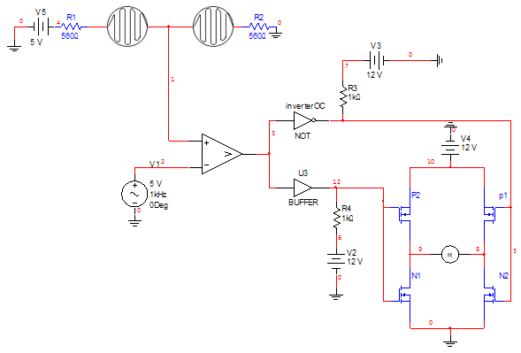
What I do not seem to grasp is how they use PWM in this schematic to turn the motor at slower speeds in both directions??? If you have a voltage of 2.5V going to the the non-inverting side of a comparator chip and on the inverting side you provide a triangle wave with 5V pk 50% duty cycle, then the output of the comparator is going to be a 50% duty cycle square wave, which as far as I can tell will only turn the motor forward and reverse at equal intervals and full speed. To me this whole design doesn't make any sense once they add PWM to the schematic.

http://www.sccs.swarthmore.edu/users/06/adem/engin/e72/lab7/

Can anyone put this into layman's terms so I can see what I am not grasping about this very simple design. Only thing I can guess is that I should maybe be using a op-amp instead of a comparator IC. Using the op-amp in a comparator configuration, then I suppose that would either make the output a positive voltage or a negative voltage with a certain duty cycle(the more I think about it, the less this even makes sense). I am so confused, just need some clarification.

Another thing I do not understand is if you look at the webpage, in the original schematic they connect both sides of the H-bridge to the output of the comparator. To me this would seem like the H-bridge would short-circuit and blow the MOSFETS. It wasn't until the second schematic that they added in an inverter to change the one side of the H-bridge to be opposite signaling of the opposing side. I don't see how this could work WITHOUT the inverter.
 
Last edited:

(*steve*)

¡sǝpodᴉʇuɐ ǝɥʇ ɹɐǝɥd
Moderator
It looks to me like the circuit uses a DC motor and applies a square wave AC signal to it. Any imbalance in the resistance of the LDRs causes the mark space ratio to change.
 
When applying pwm to a motor, its inductance will see to it that only very little current flows with a 50% duty cycle. Change the duty and you get a dc current flowing.
Introducing that 5V triangle wave to the comparator has the same effect as if they had lowered the gain to 1 in their first schematic. (Op-amp=comparator, but is slower)
Reducing the amplitude of the triangle (around a 2.5V bias) will increast the net gain of the circuit, and when you reach 0 you have a gain of 100000 like in the 1st diagram.
The correct way of making a servo comparator is to have one with a moderately high gain, but with a deadband around the neutral position. (Good for current draw too.)
While pwm is usually also good for reducing power consumption, in this application the constant 50% applied to the bridge would drain more power than neccessary.
The bridge is also a bad design; when switching the mosfet's will short out the power supply, creating current spikes & inefficiency.
Their initial bridge driver has the same drawback, but with the additional drawback that it actually won't drive the motor at all.. Their diagram must differ from reality.
All-in-all it's perfectly understandable that it's not very easy for a noob to learn from other noobs. Bad designs, mistakes, and lack of illumination of those will abound.
 
It looks to me like the circuit uses a DC motor and applies a square wave AC signal to it
Yep I get this concept. I had assumed the exact same operation.

Any imbalance in the resistance of the LDRs causes the mark space ratio to change.
Mark - space ratio is equivalent to the duty cycle of the square wave?

When applying pwm to a motor, its inductance will see to it that only very little current flows with a 50% duty cycle.
I am trying to understand this and if I get what you are saying, then to me when the square wave with a 50% duty cycle enters the H-bridge, the current flow switches from left--right to right--left across the motor and because the duty cycle is 50% then the motor will effectively remain still?
If the above is correct, then varying the duty cycle above 50% will force the motor to turn in one direction at varying speeds. The further from 50% duty cycle you get the faster the motor turns? Vice versa for the opposite direction?

The correct way of making a servo comparator is to have one with a moderately high gain, but with a deadband around the neutral position.
Can anyone link me to a decent yet simple schematic so I can learn the proper way using PWM for the motor?
Does the schematic below have the deadband that you describe. according to the site, http://cdselectronics.com/Kits/SolarTracker.htm
The 20K trimpot sets the sensitivity ie. the distance between these limits. The 100K trimpot adjusts so that these limits are symetrical around +V/2 (balance point)
solar_track_sch.jpg


edit: I want to learn about PWM and op-amps. I know one of the easiest ways to use PWM is with DC motors. hence my decision to look at this solar seeker project. If anyone has any other bright ideas for projects that I can do point me in the right direction please. I don't need for this project to succeed, I am just using it as a learning tool so I can advance my skill set.
 
Last edited:
Mark - space ratio is equivalent to the duty cycle of the square wave?
Yes.
I am trying to understand this and if I get what you are saying, then to me when the square wave with a 50% duty cycle enters the H-bridge, the current flow switches from left--right to right--left across the motor and because the duty cycle is 50% then the motor will effectively remain still?
Yes, its inductance will only allow slow variations in the current, so it will remain as a small triangle-shaped current around zero. Then there's its inertia too.
If the above is correct, then varying the duty cycle above 50% will force the motor to turn in one direction at varying speeds. The further from 50% duty cycle you get the faster the motor turns? Vice versa for the opposite direction?
Yes, it will effectively perceive the duty cycle as a percentage of the power supply voltage.
Does the schematic below have the deadband that you describe.
Yes it has an adjustable deadband (but it uses the full gain of the comparators so the motor will run full tilt when it runs, which could be ok depending on the application).
That bridge has no issues with current spikes btw., due to its emitter-follower configuration. It is a much better/ more proper design, even though there's no pwm.
 
Last edited:
Top