Maker Pro
Maker Pro

Challenge - See if you can solve this simple circuit diagram

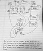
Ok I have this circuit diagram that I hooked up with 12 volt battery - 2 led's with dual terminals - low beam and high beam - high beam is 3.5 watt low beam is 1.2 watt - 1157 bayonet mount. I have 2 led flashers with battery terminal and load terminal I have a SPDT switch and a DPST switch

This circuit will be used to simulate a cars "front only" running lights, turn signal - left and right - and hazard lights.

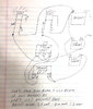
I am uploading a pic of this circuit diagram. I have another circuit diagram that fixed my first diagrams problem almost 100 percent fix. Maybe someone could explain a total 100% fix

RUNNING LIGHTS "PARKING LIGHTS" ARE ALWAYS ON IN THIS CIRCUIT

PROBLEM WITH THE FIRST DIAGRAM:
Now, this first diagram has a problem. When the turn signal is turned on, either left or right, the high beam led is hardly noticeable, very dim, will not even pass inspection as a turn signal same with the hazard lights turn them on and they are very dim hardly noticeable

I am just uploading the diagram without the partial not 100% fix. Then I would like some feedback on what you think the fix would be to make the turn signals flash at full brightness.

WHAT IS THE FIX I AM LOOKING FOR?

When the turn signals or hazard lights are on they should bling at normal speed with full brightness
not dim or hardly noticeable

Thank you for your time
 

Attachments

  • flashers_only_dim_turn_signals.jpg
    flashers_only_dim_turn_signals.jpg
    79.2 KB · Views: 34
If you were to draw the circuit diagram in a conventional way you would immediately see the problem associated with the dual LED in each instance.

It is this precise reason why, voltage fed auto lights in particular are switched in the negative AND in a particular sequence/arrangement.

Without going any further I am 100% certain of the correct arrangement, but hell, that would spoil your fun.;);)

Correct Arrangement? You mean you would not add any components?
 
Trash the 2 element LED bulb and replace with 2 single element, perhaps add some load resistance to make the flasher work on LDE loading or replace with flasher designed to work with LEDs.
No way of knowing the internal circuit of the LED combination without hacking into one and I'm not about to do that.
I do however suspect the LED bulb / flasher combination to be the heart of the problem.( feedback in old terminology)


Hello Bluejets,
I loved the video link you sent, very nice. I think I did what you mention here "perhaps add some load resistance"
I will upload my partial fix diagram now. I say partial fix because the led blinks slightly slower but the brightness is very good.

What I did was I added a diode and a 68 ohm resistor to the positive side of the led"s low beam wires

"replace with flasher designed to work with LEDs". wasn't the Amazon link I sent you a led flasher?

Tell me what you think
 

Attachments

  • flashers_only_control_turn_signal_and_hazzard_lights_fix_Edit_7.jpg
    flashers_only_control_turn_signal_and_hazzard_lights_fix_Edit_7.jpg
    350.5 KB · Views: 7
Last edited:
1001 ways . . . . . . . to wire yer liddle heart out . . . . .
https://tinyurl.com/vyddkez
Thanks 73's de Edd
Check out my schematic I drew with circuits lab web software. I used 2 relays and 2 led flashers and a DPST and SPDT switches
The relay turns off pin 87a when the turn signal or hazard lights are on pin 87 is not used. I am happy

Any ideas of what I could add to employ pin 87?
 

Attachments

  • car-cuircuit-turn-signal-hazard_2.pdf
    33.5 KB · Views: 4
Hello Bluejets,
I loved the video link you sent, very nice. I think I did what you mention here "perhaps add some load resistance"
I will upload my partial fix diagram now. I say partial fix because the led blinks slightly slower but the brightness is very good.

What I did was I added a diode and a 68 ohm resistor to the positive side of the led"s low beam wires

"replace with flasher designed to work with LEDs". wasn't the Amazon link I sent you a led flasher?

Tell me what you think
Check out my schematic I drew with circuits lab web software. I used 2 relays and 2 led flashers and a DPST and SPDT switches
The relay turns off pin 87a when the turn signal or hazard lights are on pin 87 is not used. I am happy

Any ideas of what I could add to employ pin 87?
 

Attachments

  • car-cuircuit-turn-signal-hazard_2.pdf
    33.5 KB · Views: 4
Top