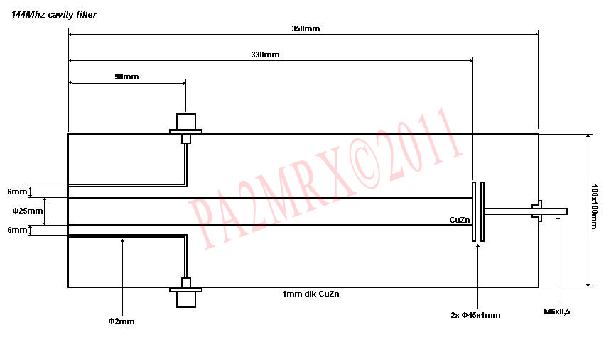
I found this hand-drawn sketch from several decades ago, which was given to me by a TV repair technician.
The resonator was intended as a "notch" or "narrow bandpass" filter to receive only one terrestial TV station (in those days, I wanted to try pick up a weak TV broadcast, BOP TV).
As it turned out, I never got around to building the resonator, as BOP ceased transmission.
However, the idea now is to use such a device for receiving (DX'ing) VHF AM transmissions (Air bands being the goal), so around 118-130 MHz or so.
What is not clear in his sketch is how the input and output are coupled to the cavity.
Would this require coax, with the center insulation being the "feed-through" spacer, or just a small hole, signal conductor centralized through the hole?
In the cavity itself, do the 'antennas' have to loop, as seen in sketches of cyclotron 'pickup' probes, or are they just straight wires?
How would I calculate dimensions for say, 132 MHz?
I remember he said the 'coin' depth was to fine-tune the resonance.
Thank you. C.