-
Categories
-
Platforms
-
Content
Just curious what brings about this condition in the first instance. Never heard it before.
Thanks for the response. Sorry was out of town at sons baseball.A battery similar to one of these should suit. If fully charged before installation, a trickle charge from track power would probably suffice to keep it topped up.
Is that the AC RMS voltage?
I can adjust the power as need on the tracks from 0-20 volts. But I am staying at about 14 to power a booster that then I power my camera and transmitter off of.G-size
G size system. I have a unique setup but I have 12-18volts on my track and up to 5amps max.
I may be confusing you with another poster, who was proposing to power the tracks with unsmoothed DC and use on-board processing on the train.I can adjust the power as need on the tracks from 0-20 volts.
1. Using a bridge and then schottky diode to Capacitor in #2 belowI may be confusing you with another poster, who was proposing to power the tracks with unsmoothed DC and use on-board processing on the train.
Suppose you have a 12V battery/supercap as backup. Would you want to have a DC track voltage less than 12V?
If you can keep the track voltage above the battery voltage at all times except during those brief glitches then there won't be a continuous discharge. Roughly how often would you expect a 1-3 sec glitch to occur? That will determine if keeping the battery charge topped up during normal running is feasible.
The TS hasn't said if his 'unique' setup track supply is AC, but if the regulator input dips below the voltage of the proposed battery then the simple diode-OR arrangement I suggested in post #8 would need to be replaced with a more complex one to prevent continuous pulsed discharge of the battery.
No it just rocks and seems to loose a solid connection from the tracks.I guess his trains take to the air for 3 seconds every now and then.
Bob
Bob,You do not need the Schottky diode after the bridge, the bridge is diodes. Presumably, your bridge is feeding a step down switching regulator to supply the 5V. The capacitor could go either of two places, before or after the step down. If before, it would required higher voltage rating. If after it would have to be larger to provide more current.
The 15V capacitor bank you linked to here:
TURNIGY VOLTAGE PROTECTOR 783333uf (3sec) STOP RC RECEIVER BROWN OUTS
https://hobbyking.com/en_us/turnigy-voltage-protector-783333uf-3sec.html
Seems to be about right. It connects directly to the bridge and to the step down converter. It is designed to provide current for a limited amount of time, which is exactly what you need.
Here is another example:
https://www.amazon.com/OTGO-Capacitor-Protection-6-4x2-5cm-2-52x0-98inch/dp/B07DFFB2HW/ref=sr_1_3?crid=34PUF3DAJ93T6&keywords=super+capacitor+bank&qid=1554755391&s=gateway&sprefix=supercapacitor+,aps,134&sr=8-3
Bob
Presumably the individual caps are series-connected, but in the post #34 link there is no visible circuitry for equalising the cap voltages as they charge/discharge 
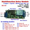
. Also, the module is rated for an input voltage of 11.1V max, so that could be a problem if the TS uses 12V on the track.the cap is rated at 2.7V.