Maker Pro
Maker Pro

Capacitive dropper circuit

Hi all,
I recently opened a led bulb which was not working and found that the leds were fine and the board was the one which had failed. It contains 10 white leds in series which individually needs about 5.5v to attain full brightness with a current draw of 30mA. So, I thought of making a dropper circuit using capacitor. I have few questions which I thought of clarifying before proceeding.
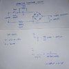
IMG_20200509_230703.JPG
My first doubt is, will this circuit practically work ?

According to the above circuit, my capacitor will be dropping around 185v and 30mA of current will be flowing through it. So my second doubt is, do we have any 'power rating' that we must consider before using a X rated capacitor?

Even if the circuit is possible, to what extent is it going to affect the power factor?


Thanks in advance.
 
Capacitive droppers do work. I have used them in the distant past.
There use is not advisable but, if you are determined to do so, see the attachment for a better circuit and explanation plus sums. Very little power will be dissipated in the capacitor and is not a concern.
 

Attachments

  • CIMG4345.JPG
    CIMG4345.JPG
    196.4 KB · Views: 34
Capacitive droppers do work. I have used them in the distant past.
There use is not advisable but, if you are determined to do so, see the attachment for a better circuit and explanation plus sums. Very little power will be dissipated in the capacitor and is not a concern.
Thanks for your reply. As per your circuit,you haven't added any resistor to limit the inrush current, have you missed it or is there any reason for not adding that?
Plz also tell me about the power factor changes the circuit will produce bcoz here we pay for reactive power also.
 
You shouldn't need to include a resistor for inrush current. Also the load is so small, I wouldn't worry about PF correction as the circuit would only be using 7 watts of power.
 
Capacitive droppers do work. I have used them in the distant past.
There use is not advisable but, if you are determined to do so, see the attachment for a better circuit and explanation plus sums. Very little power will be dissipated in the capacitor and is not a concern.
WHONOES,
It's been almost 60 years since I first studied AC theory, but I don't ever recall using the P-P voltage as the basis for calculations in similar simple circuits. For example, if the circuit only consisted of the cap directly across the supply I would have used 230V RMS as the voltage basis for any current/impedance calculations. I don't see how adding a full wave diode circuit in series would change that voltage basis.

Basically the ideal diode has no resistance so a full wave setup, as in your diagram, is basically just the equivalent of wire. Even with 10 diodes in series, I don't think the real world circuit requires P-P as the voltage basis for current/impedance calculation.

Hopefully, age hasn't clouded my thinking.
Frank
 
Have to disagree with you. The circuit will be subjected to the full peak to peak voltage of the mains supply. The 1N4007 diode that is reverse connected across the LED's protects them from the half cycle of the mains over which they will not be conducting. If it was not there, the LED's would be wrecked on the very first cycle.
 
WHONOES,
It's been almost 60 years since I first studied AC theory, but I don't ever recall using the P-P voltage as the basis for calculations in similar simple circuits. For example, if the circuit only consisted of the cap directly across the supply I would have used 230V RMS as the voltage basis for any current/impedance calculations. I don't see how adding a full wave diode circuit in series would change that voltage basis.

Basically the ideal diode has no resistance so a full wave setup, as in your diagram, is basically just the equivalent of wire. Even with 10 diodes in series, I don't think the real world circuit requires P-P as the voltage basis for current/impedance calculation.

Hopefully, age hasn't clouded my thinking.
Frank
Have to disagree with you. The circuit will be subjected to the full peak to peak voltage of the mains supply. The 1N4007 diode that is reverse connected across the LED's protects them from the half cycle of the mains over which they will not be conducting. If it was not there, the LED's would be wrecked on the very first cycle.
WHONOSE,
Sorry if my note wasn't clear....Yes, the IN4007 diode is necessary, I wasn't questioning that aspect.

What I tried to say was that using peak to peak voltage in your calculations will produce an incorrect cap value (to low).

Look at it this way. If the circuit had no diodes at-all, but just had a cap across the 230v input. The resulting current is 10.8 ma RMS. (150nf Xc @50hz is 21,221 ohms, 230/21221=10.8ma.)

The LEDs require 30ma RMS, inserting the 10 white leds/1n4007 in series with that cap is not going to increase the current flow to 30ma. It's going to decrease the current.

BTW, the circuit probably should have a bleeder resistor across the cap for safety to reduce chance of getting shocked if the bulb is removed from it's socket. Probably a 1 meg resistor would work.
Frank
 
One other problem I realized after seeing the improvement suggested by burtus:

Each branch of diode circuitry only gets current flow for half a cycle. Therefore, to get an equivalent of 30ma (RMS) through each diode branch the total current for the circuit should be designed to allow a total of 60ma (RMS). Hopefully that does not exceed any peak specifications for the LEDs.

Frank
 
Top