Maker Pro
Maker Pro

Canon Camera battery help

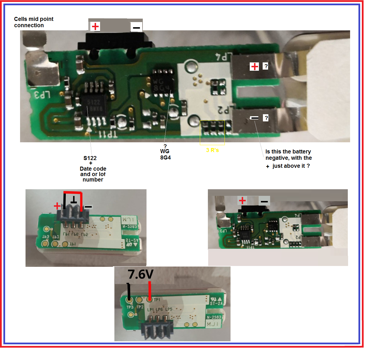
I shorted the + - external connections on the battery for less than half a second. Now the battery is not charging, it is not being recognised in the charger. The camera doesn't see it either. I've opened the battery pack and there are no obvious signs of damage. I am getting reading of DC 7.6v on parts of the pcb (which is correct), but the external terminals are reading 0.151v. The images I've provided show the unit. If somebody can help and they need me to check basic things with a multimeter I can do that, like connecting a to b and providing the reading info.

I know I am a dumbo but I'd be grateful for anybody's help.
 

Attachments

  • 1.jpg
    1.jpg
    60.1 KB · Views: 6
  • 2.jpg
    2.jpg
    71.3 KB · Views: 6
  • 3.jpg
    3.jpg
    160.1 KB · Views: 6
  • 4.jpg
    4.jpg
    197.5 KB · Views: 9
Is there any set of checks I can do to understand which component on the IC has died, if any, given it was a short and I can still read full power in the places I've shown in the images I attached, I was hoping I could replace a part and bring the battery back to life.
 
Sir Baracas . . .

Correct me on any mark up errors.
You can see that bottom photo is telling you that the battery voltage is making it all the way across the board to those TP1 anf TP3 test points.
You stopped short of telling us if the neg or positive then made it down to the black connector.
I'm suspecting that the + makes the trip to the connector, and that you are loosing the negative path.
BECAUSE . . . . normal Li Ion design protocol is to monitor and switch the negative output power buss.
I believe that it will be found that the negative power flow will pass thru two series POWER FET's with VERY - VERY low RDS-on characteristics when turned on. The negative buss flow, also then goes thru a very low resistance current shunt before finally reaching the negative output connector.
Operation is this way . . . . .
That S122 should be your battery management IC to ascertain the state of charge on the individual battery cells. If low it charges, and when all is up to charged state it will activate the two series POWER FET's to give a completed power path from charger negative output to that black connectors 1 terminal.

Then the camera should then have power to work . . . . UNTIL . . . .the monitoring of the Li Ion cells , detects a progressed discharge of then having less than 2.5V from a cell.
Then it will drop FET gate bias and then a FET stops conduction and your camera is deprived of power and dead until you recharge the battery, or sometimes a rest in a warm area . . . . .z z z z z z z . . . . will give enough bounce back for just a wee bit more use time, later on.

Another aspect of the FET switching is the mentioned series shunt resistors taking the proportional voltage that is developed by the amount of power being pulled and feeding info back to the battery management IC. If it detects excess current pull, it also can open up that negative buss with a dropping of FET.
gate drive.This last application, is actually more in line with a power tool . . .drill . . .saw . . ., when it is being grossly loaded down.

I think that ? WG8G4 ? is being a dual POWER FET and your DEAD short was too much for it to handle and it is now vaporized of its die inside.
I am also wanting to think that for its power handling ability, that it is having a metal heat sinking plate on its un viewable side and depends on being soldered to a foil plane for additional lateral heat dispersion / dissipation.
Pulling one off, reads synonymous with the need / use of a hot air heat wand.
They do make 2 cell aftermarket boards like this . . . . . but . . .BOY . . . the mechanical fitting aspect !

https://www.batteryspace.com/protec...sjU6d3C1wzS0UIXiMcXZ_6IQYtuizn50aAnQvEALw_wcB


Confirm if it is being your negative power feed thru that is being lost to the black connector.

RE- REFERENCES WITH MARKUPS

Direct . . . . hot link to larger Images

https://i.postimg.cc/VYkGXhJp/Canon-Camera-Battery.png

Canon-Camera-Battery.png


73's de Edd . . . . .

What kind of cruel, demented person was it who put an "s" in the spelling of lisp ? Since its gonna come out as a difficult Lith-p .

.
 
Wow,

That was just amazing. I might be beyond me but I am going to keep trying.

I apologise for not providing better overall images.

here are some more images.

They should the general construction of the battery and the unfolded board when I cut the connection going from the board to the booth of the battery.

While these images don't fully show the parts I hope they show what parts are where becasue you mentioned a heat sink and I can't see one at the opposite side of the WG8G4
 

Attachments

  • IMG_20211023_204928_resized_20211023_085016889.jpg
    IMG_20211023_204928_resized_20211023_085016889.jpg
    183.8 KB · Views: 3
  • IMG_20211024_210257_resized_20211024_090428110.jpg
    IMG_20211024_210257_resized_20211024_090428110.jpg
    185.5 KB · Views: 2
  • IMG_20211024_210304_resized_20211024_090412337.jpg
    IMG_20211024_210304_resized_20211024_090412337.jpg
    150.3 KB · Views: 2
  • IMG_20211024_210328_resized_20211024_090352797.jpg
    IMG_20211024_210328_resized_20211024_090352797.jpg
    126.4 KB · Views: 1
I've been trying to upload some other images that would give you a better quality look at the board, but I am getting an error everytme I upload more images. I think it's a restriction of the forum.
 
You are correct it is a WG8G4. I cannot load any more images, they keep giving me an error.
The negative - terminal is as in your reply.

I loaded to hotlink. Here they are.

https://postimg.cc/gallery/dLcmtGm

Is there a way to check if the w48G4 or the S122 are broken, and could I buy these parts?
 
Sir Baracas . . .

Correct me on any mark up errors.
You can see that bottom photo is telling you that the battery voltage is making it all the way across the board to those TP1 anf TP3 test points.
You stopped short of telling us if the neg or positive then made it down to the black connector.
I'm suspecting that the + makes the trip to the connector, and that you are loosing the negative path.
BECAUSE . . . . normal Li Ion design protocol is to monitor and switch the negative output power buss.
I believe that it will be found that the negative power flow will pass thru two series POWER FET's with VERY - VERY low RDS-on characteristics when turned on. The negative buss flow, also then goes thru a very low resistance current shunt before finally reaching the negative output connector.
Operation is this way . . . . .
That S122 should be your battery management IC to ascertain the state of charge on the individual battery cells. If low it charges, and when all is up to charged state it will activate the two series POWER FET's to give a completed power path from charger negative output to that black connectors 1 terminal.

Then the camera should then have power to work . . . . UNTIL . . . .the monitoring of the Li Ion cells , detects a progressed discharge of then having less than 2.5V from a cell.
Then it will drop FET gate bias and then a FET stops conduction and your camera is deprived of power and dead until you recharge the battery, or sometimes a rest in a warm area . . . . .z z z z z z z . . . . will give enough bounce back for just a wee bit more use time, later on.

Another aspect of the FET switching is the mentioned series shunt resistors taking the proportional voltage that is developed by the amount of power being pulled and feeding info back to the battery management IC. If it detects excess current pull, it also can open up that negative buss with a dropping of FET.
gate drive.This last application, is actually more in line with a power tool . . .drill . . .saw . . ., when it is being grossly loaded down.

I think that ? WG8G4 ? is being a dual POWER FET and your DEAD short was too much for it to handle and it is now vaporized of its die inside.
I am also wanting to think that for its power handling ability, that it is having a metal heat sinking plate on its un viewable side and depends on being soldered to a foil plane for additional lateral heat dispersion / dissipation.
Pulling one off, reads synonymous with the need / use of a hot air heat wand.
They do make 2 cell aftermarket boards like this . . . . . but . . .BOY . . . the mechanical fitting aspect !

https://www.batteryspace.com/protec...sjU6d3C1wzS0UIXiMcXZ_6IQYtuizn50aAnQvEALw_wcB


Confirm if it is being your negative power feed thru that is being lost to the black connector.

RE- REFERENCES WITH MARKUPS

Direct . . . . hot link to larger Images

https://i.postimg.cc/VYkGXhJp/Canon-Camera-Battery.png

Canon-Camera-Battery.png


73's de Edd . . . . .

What kind of cruel, demented person was it who put an "s" in the spelling of lisp ? Since its gonna come out as a difficult Lith-p .

.
 
Hi,

I have attached a PDF because I was able to include comments and image markups much easier. I hope this answers your questions. Thanks for all the help so far. I hope we can get this fixed.
 

Attachments

  • Battery Update.pdf
    275.2 KB · Views: 1
I ended up doing this becasue somebody said it might kick the battery back into life. I think you alluded to it where providing power to one of the Ics would bring it out of sleep mode.
20211027_222957.jpg
 

bertus

Moderator
Hello,

From the last picture, I would say, that it can be dangerous.
When the Lithium battery heats up, it may catch fire.

Bertus
 
After connecting the battery pack that I built to the camera battery (after about 5 mins) I disconnected it, because I was going to bed. I inserted the camera battery into the charger and the charger's 'charging light lit for a moment. The insertion of the canon battery was awkward because it's not properly reassembled. I will attached my homemade pack to the canon battery for a few hours tomorrow and then try it in the charger, hopefully it will have taken more of a charge from the my battery pack to allow it to continue to charge in the canon charger. I'll also know to insert the canon battery in a better way. I will keep you posted.
 
Hello,

From the last picture, I would say, that it can be dangerous.
When the Lithium battery heats up, it may catch fire.

Bertus
I will only use this temporary charge way to temporarily boost the camera battery so it will be recognised by the camera's charger. I will not leave the battery pack that I made and the lithium battery connected if I am not beside them all the time. Thanks for your advice, it is appreciated.
 
I've attached 4 images. The first is before I connected the camera battery to the battery pack I made and the reading is 0.152. The second is after the camera battery had been connected to the DIY battery pack for about 3 hours and it's reading 7.62v. The third is the camera battery in the charger, but the charger's light is not coming on. The forth shows a spurious battery and the charger working.
20211027_213957.jpg20211028_125333.jpg20211028_125427.jpg20211028_130011.jpg
 
Last edited:

Similar threads

T
Replies
1
Views
3K
Fred McKenzie
F
A
2
Replies
26
Views
2K
Adrian Tuddenham
A
G
Replies
10
Views
1K
Rudolf
R
Top