Maker Pro
Maker Pro

Calculating voltage divider bias, using a thermistor for transistor circuit

hey all, i have been working on this problem for days now...and it should not be this hard but i can not get it to work.

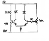
I need to design a simple circuit so that when a thermistor is heated with a lighter, its resistance drops and creates a bias voltage of at least .7V volts through an npn transistor, and then this transistor lights an LED.

Could someone please explain this circuit, how it works, and perhaps even draw a simple schematic? I can only thank you so so much.

I can't even get the right resistor value, but here are the values you have

Resistance of thermistor when at room temperature: 4500ohms,
Resistance of thermistor when heated up: 3500 ohms.

Resistance of collector: 1000 ohms

VCC: 5 volts

I need to find R2, please help lead me through a voltage divider calculation and please help me draw out the schematic. I've spent way too much time on this
 
Vout = Vcc*(R2/R2+R1), just plug in the values or rearrange the formula as needed. I'm assuming your setting this up as potential divider?

------------------------------------------------ VCC
|
|
R1
|
|
--------------------------- Vout
|
|
R2
|
|
-------------------------------------------- GND
 
Yes Gav you are correct, and I have calculated that many times but the values do not work!

I am using 3904 NPN transistor
Thermistor resistance at room temperature = 4.7k
Thermistor resistance when heated up: 3.7k

I want the thermistor to trigger the base when it is heated up....i swear i have worked on this for 8 hours now...please illustrate it for me
 
You can't switch on the led with your single Bjt. I could do it with two (e.g- Vthermistor at 25C causes Q1 to saturate so Q2 is in cut off condition and led is off).

I'm guessing you're missing something else for your circuit.
 
could you please draw that out for me? I have tried a two transistor circuit nad i haven't been able to get that to work either
 
Try this Bjt circuit. Its a simplified Schmitt trigger Bjt (stupid schmitt; having no hysteresis or precission).

Pay attention to Q2's collector; you must put the led there.
 

Attachments

  • stupid-schmitt.png
    stupid-schmitt.png
    2.2 KB · Views: 192
Last edited:
so the base isn't used in the first transistor? Where would i put the thermistor? In R1? and how do i calculate R2 value?
 
Connection is made from your Vout. The Bjts are for switching on/off the led.

A few more days and you should have it done, huh;)
 
Last edited:
You will need a comparator which can be dedicated circuit or made from two transistors.

Assume that the thermistor is 4000 ohm (the mid point) and that it has 2V across it, then 3V will need to be across the series resistor so it will need to be 4000*3/2 = 6000 ohm (use 6200) connect to the base of a transistor.

Take a 10k potentiometer and connect between Vcc and ground. Connect the slider to the base of another transitor. Connect the emitters together and connect to ground via a 100 (?) ohm resistor.

One resistor needs to go to Vcc an the other to Vcc via a load such as a led.

The potentiometer should adjusted to switch at the right temperature.

Some positive feedback could be added to give a dead band and rapid switching.
 
Vout = Vcc*(R2/R2+R1), just plug in the values or rearrange the formula as needed. I'm assuming your setting this up as potential divider?

------------------------------------------------ VCC
|
|
R1
|
|
--------------------------- Vout
|
|
R2
|
|
-------------------------------------------- GND


If you use this circuit with the NTC as R1 (4500ohm cold and 3500ohm warm) R2 should be in the interval from 470 to 560 ohms, to connect the base of the transistor to the output, Vout. This is based on Vcc = 5V. Doing it this way you'll never have an accurate setpoint for the turn on of the transistor.
 
You will need a comparator which can be dedicated circuit or made from two transistors.

Assume that the thermistor is 4000 ohm (the mid point) and that it has 2V across it, then 3V will need to be across the series resistor so it will need to be 4000*3/2 = 6000 ohm (use 6200) connect to the base of a transistor.

Take a 10k potentiometer and connect between Vcc and ground. Connect the slider to the base of another transitor. Connect the emitters together and connect to ground via a 100 (?) ohm resistor.

One resistor needs to go to Vcc an the other to Vcc via a load such as a led.

The potentiometer should adjusted to switch at the right temperature.

Some positive feedback could be added to give a dead band and rapid switching.

Thank you for the advice duke, but it still won't work..

The LED turns on and off depending on the potentiometers resistance, but the thermistor has no affect on anything! I have taken a picture of my circuit setup. Please let me know what you think, and a couple questions

1: does the resistor to VCC and the other lead to the LED connect to the collector of the 2nd transistor?

BTW my VCC is ~ 5.8V and the potentiometers base resistance is about 4K and drops to 2.5k when heated.

Please help me out!

img20130505175653.jpg
 
Please post a schematics on our circuit.

That way we can see what your intentions are, and compare with what you have done.
 
I post an idea of the circuit I described. I have added a 1k resistor to the base on one transistor to protect it in case you turn the voltage up too high on the potentiometer.

If the circuit switches when the potentiometer is adjusted, then it appears to be working correctly.

Measure the voltage across the thermistor and see if it changes with temperature. If it changes very little you may need to use a comparator or op-amp
 

Attachments

  • comparator3.png
    comparator3.png
    3 KB · Views: 569
Top